Question:
What stops the FJR charging system from overcharging the battery? From the info I've seen it's just a constant voltage system providing 14.4 volts or so. As long as it's not overloaded it delivers a fairly constant voltage. The current output increases and peaks at around 5K rpm.
I don't understand why this system doesn't overcharge the battery? If the battery is fully charged and you ride for a few hours it would seem that the battery might be overcharged.
Don't see how the FJR's system is all that different from a manual charger I use in my garage. Even for the 2 amp output you can overcharge a small battery. It will continue to hammer the battery with 14.4 volts even as the current drops to less than 0.5 amps.
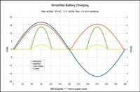
A simple (dumb) garage charger just rectifies a roughly 12V rms AC supply. There is essentially only circuit resistance limiting the charging current, the graph below shows what is going on (this is only intended to show the principles, many approximations in here).
(Click on image for larger view)

The current doesn't go down much as it overcharges, so the energy goes into heat and/or undesirable chemical reactions. Neither is good for the battery.
The bike uses a regulator to limit the voltage offered to the battery. Provided the charger doesn't exceed 14.x volts, the battery will decide how much current to take. A non-voltage regulated charger can and will overcharge the battery. The bike's won't (unless the regulation circuit fails).
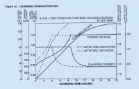
This graph of a constant current/constant voltage charger (lifted from
a Yuasa document) shows how the "REGULATED CURRENT" reduces as the battery nears full charge, the charger having switched from "constant current" to "constant voltage".

(The document refers to a slightly different battery technology from that of our bikes', but the principles are the same.)
The charger is shown with a constant current of 0.1 C Amps. 'C' refers to the battery's Ampere-Hours figure, 14 in the case of the FJR's OEM 14AH battery, so the example charge current is limited at 1.4A. (Very low for automotive use, but, again, this graph was for a non-automotive battery.) When the battery terminal voltage reaches the charger's voltage limit (15 in the example), the voltage remains constant but the battery draws a reducing current as its charge increases.
Incidentally, the
maximum current on our bikes is determined not by the regulator but by the alternator. As the alternator speed increases, so does the open circuit voltage (up to something like 100[?] volts at the maximum engine speed). But, as the speed increases so does the inductive reactance. Even with a short circuit directly on the alternator, the current wouldn't vary much from almost no speed to full speed. Obviously when there's a battery voltage opposing the alternator (as is the norm), the speed must be sufficient to overcome this. However, much above Yamaha's quoted engine speed for the alternator current specification (5000 rpm), the charging current can't go up significantly. (This is a simplification, but hopefully helps explain what is going on.)
The Gen I uses a "shunt regulator" that shunts the alternator current to ground to regulate the voltage (as ionbeam said in his post above), the Gen II uses a "series regulator" that open-circuits its output to the battery.


