Stator Installation

Yamaha FJR Motorcycle Forum

Help Support Yamaha FJR Motorcycle Forum:

This site may earn a commission from merchant affiliate links, including eBay, Amazon, and others.
Another little thing about installing any stator in the FJR, this quote is from a message during the first ElectroSport GB:

Wasn't there an issue with the Electro Sport Stator scraping metal on initial startup?
Here is a compilation of text from different areas of my reply:

When I pulled the stator cover off my FJR I was shocked to see this groove cut into the rotor by the stator wire holding bracket.

Rotor.jpg


You guys that had a squealing noise for a few minutes after startup now probably know what you were hearing. Hope your oil filter pulled out the lathe shavings.

Pay close attention to the stator wire retaining bracket and don't let it bend when you screw down the Phillips head screw. The ElectroSport stator has insufficient length (IMO) between the stator and the black feed-thru rubber gasket (rubber plug?). One intrepid person spent a few minutes working the rubber gasket further up the wires and had no problem getting the bracket to screw down without bending. It took me several tries, bending the bracket back into shape for each new try. I finally got it done with no interference problem. In my case I already had a groove cut in my rotor from Yamaha's original factory install.

In the following picture, shamelessly ripped off from beeroux without his permission – the nefarious bracket is up by the orange sealant, the bracket is held down by the big ol’ Philips screw. The offending part of the bracket is a small 'L' shaped tip at the bottom of the bracket, just out of sight in this picture.

DSCN3506.JPG


Last edited by a moderator:
Ionbeam is right, I think.

I was going to modify that wire bracket somehow but for the life of me couldn't see any wear or where exactly the bracket was making contact with the rotor.

Just be careful, and like Ion sez: make sure to install it properly so as not to cause more grooving.

BTW, my rotor has the exact same groove cut into it. Poor design in my opinion.

GZ

 
for the life of me couldn't see any wear or where exactly the bracket was making contact with the rotor.
It's a pisser that the only time you can see the bracket/rotor interference is when the parts are put together, but then you can't see the bracket :blink:

Since I don't have a life, ;) I took some time with my calipers, the rotor and the stator housing to figure out what happened. I was able to get an exact measurement match between the groove on the rotor and the tip of the wire bracket. When I ran a straight-edge down the wire retainer bracket I could see that it was ever so slightly bent out toward the stator ring and it was clear that the wires behind the bracket were the cause. I used a precision ground #3 soft faced persuader with 16.3792 lbs of force to correct the bracket from 98.643 degrees back to intended 90.000 degrees. It had a happy ending with no metallic squeal, no grinding and no metal bits in the oil or filter. :yahoo:

 
Last edited by a moderator:
I'd like to see a photo of a used OEM stator showing the side opposite the three-wire connection -- the side facing inward to the right. I'm assuming the oil spraying out from the head of the large bolt securing the generator rotor to the crankshaft bathes the left side of the stator.

I'm not sure that the dark residue on the stator wiring insulation offers any clue about the condition of the insulation.

 
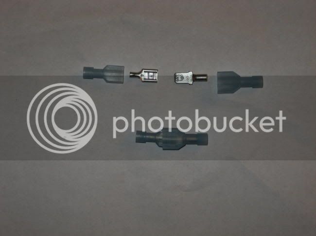
In going through my parts box to lay out my stator install (and horn install) I happened upon these connectors:

IMG_04282.jpg


I'm going to use these to connect the "cut" wires to attach the new stator wires to the OEM wires running to the rectifier/regulator. They come as shown on the bottom - I pulled them apart and will crimp and solder the wires to the connectors, run the blue plastic over the connectors and will probably shrink wrap the whole mess. I got these (and almost all of me electrical stuff) from a boat supply place. Heck, I figure this stuff is made for a wet environment anyway.

 
Jestal,

in the spirit of your knowledge, I've edited my post as a precaution.

However, my metallurgist pals think you're a tad paranoid.

Which is OK, as many of us take our wrenching past any "normal" state of diligence.

Yourself included.

Towards this state of excess I endeavor.

GZ

 
Nice write up George. Cudos to Matt, Art and Greg for their assists in clarification. And those other guys too. ;)

Almost makes me want to buy a stator upgrade.

 
Jestal,

I totally believe you. I really do.

Certainly did I flush and scrub and flush again all contaminants from the stator cover.

I did it with brake cleaner over a gurney in my back yard. <G>

You think I jest, just ask GunMD.

No re-circulated solvent baths were harmed in the making of this write-up.

All jesting aside, I think Jestal makes a good point. Only use 3M where you can absolutely positively flush all micron oxide away from finished installation.

GZ

 
I have been replacing stators for 35 years and have noted that the stress that the regulator has gone through during the demise of the stator in many cases will cause the regulator to possibly fail soon. In other words , if you replace the stator , it is wise to replace the regulator.
I agree that it would be a good idea to replace the rectifier if your stator failed. Most of us are doing this prior to the stator failing, and are doing this to hopefully prevent the stator from failing due to adding alot of electrical farkles. Would you think it would be nessisary in this situation? I've got about 20k on my new stator and my system seems to be doing fine, but I certainly don't want to be stranded because my rectifier goes AWOL.
One of the things I have seen in the past is if the regulator is marginal you will see a slightly high output when you check the battery with a meter. Normally the output with the lights on high beem and the engine running at 3000 rpm is 14,8 volts. If you see anything higher than this such as 15 volts I would immediately shut down the bike and check the resistance on the three legs of the stator, you can do this by simply disconnecting the stator plug at the rectifier and doing resistance readings between the three white/or yellow wires. They should be identical reading. Then check from each pin to ground. They should read open or basically ( 0) . If this is the case then you replace the regulator. If the voltage read across the battery is read less than 14 volts at 3000rpm the regulator is probably bad. No one wants to be on the side of the road so I recommend anyone who rides to invest in a pocket tester. Most radio shack stores carry a clam shell tester for under $30 and it fits under the seat or in the side pouch very nicely. I hope this helps.

 
I would expect that the ElectroSport stator includes larger cross-section wire in the windings. It may also include wiring insulation with a higher temperature rating. The resistance heating of the windings is governed by the (I squared * R) relationship. A 20% increase in the winding currents results in a (1.2 * 1.2 = 1.44) 44% increase in the winding resistance heat. This can be offset to some extent by using larger wire with a smaller R value.

The oil sprayed on the left side of the stator arrives in an inconsistent manner. The oil flows out the end of the crankshaft into the large bolt securing the generator rotor to the crankshaft. The hollow bolt has a small hole in one of the sides of its head. As the bolt spins with the crankshaft oil is sprayed out onto the the left side of the stator. But all sections of the stator are not bathed equally. The generator cover has three mounting lugs projecting out onto which the stator is bolted. The three lugs don't form a continuous circle -- there are three gaps in the lugs. As the oil sprays out from the bolt it passes through the three gaps onto the stator. But the oil also sprays onto the mounting lugs and doesn't hit the stator windings in those three locations. So the cooling effect from the oil is not consistent over the entire stator assembly. This may help explain why different portions of the stator are darker and lighter in appearance.

One can see how the oil flows onto the stator on pages 2-28, 29, and 30 in an earlier service manual.

 
I had a rough day at work yesterday, dealing with a meth lab fire. Yowza.

So why I bothered to pen 2 articles is beyond me.<G>

I like how we've gotten a bit of Wiki going on here. It's good, I appreciate it.

So, as jestal mentioned, Scoth Brite pads have no place in our shops. I Googled it just now and found overwhelming evidence. Sure, you can use it if you can be certain to remove ALL micron material. But who can really ensure that? Best to just not use them.

I've edited the article and will be replacing the tools pic shortly.

Thanks for all the wisdom folks.

GZ

 
For a given rotor rpm the stator currents peak when the regulator is operating to limit the DC output voltage. Regulator thyristors connected to each of the three winding circuits are shorted by the regulator controller. When a thyristor is switched on (shorted) the impedance in that winding circuit is at its minimum. So the winding current peaks whenever the thyristor is switched on.

The average current level in the stator windings is a function of rotor rpm, regulator operation, and system DC loading. It's likely the maximum average winding currents for a given rotor rpm occur when the system loading is fairly high but not high enough to stop the regulator from actuating the thyristors to limit the DC output voltage.

A good description of the FJR regulator (PDF document) is provided here:

https://www.shindengen.com/resources/Conten...nts/art-1-2.pdf

 
The ElectroSport stator has insufficient length (IMO) between the stator and the black feed-thru rubber gasket (rubber plug?). One intrepid person spent a few minutes working the rubber gasket further up the wires and had no problem getting the bracket to screw down without bending.
Very highly recomended step. I'm in the process of installing my stator and I took the time to carefully test fit and measure everything to ensure proper fit and no grinding of parts. In doing so I noticed that the length of the wire referenced above is too short.

I measured the length of the wire from where it bends away from the stator up to the rubber gromet on both the original stator and the new electrosport unit. The new electrosport unit was approx 1/4" shorter. As soon as I tried to tighten the metal guide down it became obvious that this shortness was trying to force the metal tab out into the rotor, which of course causes the grinding problem.

It is indeed quite easy to shift the gromet out on the wires. the trick is to go to the very end of the cable where the spade connectoers are. The black outer sheath is taped into place to prevent it from sliding. This in turn prevents it from sliding up and you from easily sliding the gromet up. Take the electrical tape off, slide the sheath up a bit, now the rubber gromet can be worked up the wire a bit. EZ.

When you go to bolt the metal tang in place it should easily drop into place without any undo stress being applied to the wires. Once installed slide the sheath back down into the rubber gromet housing and retape at the top.

- - - - - - - - - - - - - - - - - - - - - - - - - - - - - - - -

On another note. I have chosen to cut the cable end off the existing stator and then attach to the new stator. I considered carefully how to do so, in the end I decided to use crimp on splice connectors, followed by a touch of solder to ensure a perfect connection.

While I have no doubt the spade connectors crimped on would be suitable, I have had issues with other bikes in the past where a connector such as this has been present have caused problems.

On the old bike there was a 3-prong connector with these spade connectors in it. Unfortunately this connector was near to the rear wheel and over the years the connectors would oxidize a bit, this in turn would cause resistance, which in turn generated heat. Eventually the connector would literally melt. If the connector was well maintained (good clean tight contact) and packed with Di-electric grease it was fine. However, I was one of many people who got tired of deailing with this problem. So I eliminated the connector and spliced the wires together to avoid any problems whatsoever.

Fast forward to now; Any electrical work I am doing is intended to last, no matter what. So I've clipped the spade terminals off the electrosport and crimped+soldered a splice connector to connect it to the end of the wires coming from the old connector. I cut the old connector off the old stator near the stator end of wire so I have lots of extra wire length. If I ever need to replace the stator, I'll take the time to snip and resplice again. I'm sure the crimp on spades mentioned would work fine, but I would at least recomend packing them with dielectric grease to ensure a good corrosion and oxidization free connection for a long time.

All of the above --> My $0.02 worth.

- Colin

 
Yeah, after talking to Beeroux about this a bit, I see where this should be waterproofed. I'm not as concered about it as he is, but I see where he's coming from. I think that waterproofing the connection point between the stator wires and the rectifier with a silicone sealant is probably in order.

Vecter,

What did you end up doing to waterproof your connections ?

Being in Arizona, do you ever ride your bike in the rain ?

 
Last edited by a moderator:
Do I ever ride in the rain? Yeah, I've been known to get a little wet.... B) As an LD rider, it comes with the territory. I've spent hours in the rain before, well past my rain gear being able to keep me dry, and have ridden thousands of miles in the rain.

Honestly, shortly after posting I was going to waterproof it, I decided I really didn't need to do this. I mean, its not going to get that wet up there is it? Well, after hearing of Doug Chapman having a mysterious electrical problem in the 07 Iron Butt that seemed to sort itself out when the bike dried off, I decided once again I really need to water seal this.

I haven't done it yet, but I plan on putting a little dielectric grease on the connectors, then coating the whole opening to the rectifier with RTV silicon. Its on my list of things to get done before next years rally season.

 
Honestly, shortly after posting I was going to waterproof it, I decided I really didn't need to do this. I mean, its not going to get that wet up there is it? Well, after hearing of Doug Chapman having a mysterious electrical problem in the 07 Iron Butt that seemed to sort itself out when the bike dried off, I decided once again I really need to water seal this.
And I've never really figured out what got wet exactly.

I surmise that something got soaked while the bike was parked and not moving in the deluges we got prior to the IBR start. In the past, with similar thousands of miles in wet and rainy weather, nothing similar has ever happened and charging continued to improve as the bike was ridden in this instance.

It also could have been partial grounding of my datel meter which had a broken and split case. Perhaps the display was inaccurate all the while my bike was starting and charging normally.

I think sealing out water is a good thing to do just as a precaution on any onboard electrical connections.

dougc

 
Last edited by a moderator:
Top