yamafitter
Reigning NERDS Granite Lane Gold Medalist
I need some assistance. A while back when doing a TBS I was having some problems with #1 cylinder and ended up having to completely close the air screw while having #3 open roughly 1 full turn. This also caused some issues with too high an idle speed that I could not adjust with the idle adjustment screw.
I aquired a Vacuummate on the advise of the National Service Manager for Yamaha Canada who also happening to be a fellow club member and when going over the vacuum readings I was getting some very strange readings from #1 cylinder that I didn't really understand. The Vacuummate uses pressure transducers that have a very quick response time and the instrument also has a dynamic mode that allows comparison of the vacuum pulses between the cyinders. The vacuum pulse on #1 cylinder appeared to have less vacuum being developed but also less vacuum being lost which gave a shorter pulse duration that the other three cylinders.
It was looking like I was going to have to pull the throttle body assembly off but before I went too far I tried some throttle body cleaner after having a discussion with Ray over what could be a root cause thinking that there may be a blockage in the air screw circuit. When I went to put the straw down into the vaccum ports I was able to insert the straw into the ports on three of the cylinders but found what appears to be an installed restictor on #1 cylinder....


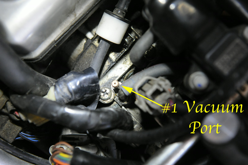
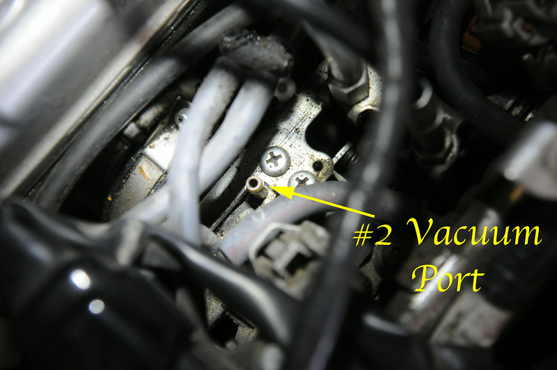
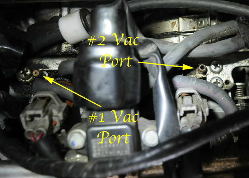
Here is a photo showing both #1 and #2 Vacuum port....

What I am trying to determine at this point is the restriction in the #1 Vac port normal? I was able with some effort to remove it and then the Vacuummate showed a reading in agreement with the other cylinders and I was able to get some adjustment with the #1 air screw to achieve a TBS and lower my idle speed with the idle adjustment screw.
What I would like is the next time any Gen II owner has the tank off their FJR could you please have a look and see if there appears to be a restrictor in the #1 Vacuum port. I have a McCruise Cruise Control System and I double checked the instructions thinking the restriction was part of that installation but that is not the case and I can't think of any other valid reason for the restrictor to be there. There are enough differences in the throttle bodies between Gen I & II that a comparison with the Gen I Vac ports on the throttle bodies may not be definitive. It would be best if this was done by a Gen II owner.
The instrumentation shows that this restriction was definitely attenuating the vacuum signal so my interest is peaked to see what is the stock arrangement on another Gen II.
Thanks.
I aquired a Vacuummate on the advise of the National Service Manager for Yamaha Canada who also happening to be a fellow club member and when going over the vacuum readings I was getting some very strange readings from #1 cylinder that I didn't really understand. The Vacuummate uses pressure transducers that have a very quick response time and the instrument also has a dynamic mode that allows comparison of the vacuum pulses between the cyinders. The vacuum pulse on #1 cylinder appeared to have less vacuum being developed but also less vacuum being lost which gave a shorter pulse duration that the other three cylinders.
It was looking like I was going to have to pull the throttle body assembly off but before I went too far I tried some throttle body cleaner after having a discussion with Ray over what could be a root cause thinking that there may be a blockage in the air screw circuit. When I went to put the straw down into the vaccum ports I was able to insert the straw into the ports on three of the cylinders but found what appears to be an installed restictor on #1 cylinder....


Here is a photo showing both #1 and #2 Vacuum port....

What I am trying to determine at this point is the restriction in the #1 Vac port normal? I was able with some effort to remove it and then the Vacuummate showed a reading in agreement with the other cylinders and I was able to get some adjustment with the #1 air screw to achieve a TBS and lower my idle speed with the idle adjustment screw.
What I would like is the next time any Gen II owner has the tank off their FJR could you please have a look and see if there appears to be a restrictor in the #1 Vacuum port. I have a McCruise Cruise Control System and I double checked the instructions thinking the restriction was part of that installation but that is not the case and I can't think of any other valid reason for the restrictor to be there. There are enough differences in the throttle bodies between Gen I & II that a comparison with the Gen I Vac ports on the throttle bodies may not be definitive. It would be best if this was done by a Gen II owner.
The instrumentation shows that this restriction was definitely attenuating the vacuum signal so my interest is peaked to see what is the stock arrangement on another Gen II.
Thanks.
Last edited by a moderator:


![fjackets Real Lambskin Leather Biker Jacket — Quilted Cafe Racer Zip Up Moto Leather Jackets For Men | [1100085] Johnson Brown, XL](https://m.media-amazon.com/images/I/41I7Pm1f+vL._SL500_.jpg)


