


Roy Epperson
Well-known member
So I've read all the posts on the Audiovox installs and did not find a recommended part number(s) other than "get a quality one".
Any recommendations where to find one and recommended part numbers? The couple I found going to 3 different stores this afternoon where on the "you oughta replace that with a better one" list......
Roy
Any recommendations where to find one and recommended part numbers? The couple I found going to 3 different stores this afternoon where on the "you oughta replace that with a better one" list......
Roy
Last edited by a moderator:
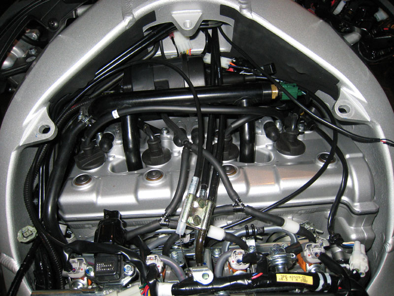

") . Why do you have 2 hoses connected? You don't need the canister to be "in the flow" of the air between the servo and the vacuum source on the engine to work. If the canister is connected into the servo's vacuum line at any point, in any way (as long as it is on the servo's side of the check valve), then it will work.
. Why do you have 2 hoses connected? You don't need the canister to be "in the flow" of the air between the servo and the vacuum source on the engine to work. If the canister is connected into the servo's vacuum line at any point, in any way (as long as it is on the servo's side of the check valve), then it will work.