Where is the Gen 1 high beam relay?

Yamaha FJR Motorcycle Forum

Help Support Yamaha FJR Motorcycle Forum:

This site may earn a commission from merchant affiliate links, including eBay, Amazon, and others.

Murph

Well-known member
Joined
Mar 26, 2007
Messages
723
Reaction score
1
Location
Gig Harbor, WA
I've checked the service manual and searched online but am not seeing exactly where the high beam relay is on my Gen 1.

 
Last edited by a moderator:
Good question.

The SM has a photo in it that shows it's location, but it's not accurate. Neither is the SM's wiring diagram. :angry2: Don't ask me how I know.

I can tell you it IS one of the five relays mounted on the front subframe behind the gauge cluster. I'll see if I can find a photo.

Edit..........

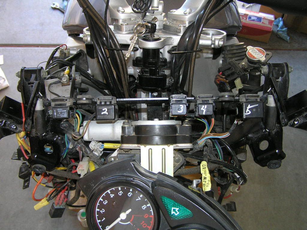
Ok, so here's a photo. You can see the 5 relays that are mounted across the top of the front subframe, just in front of (or behind) the gauge cluster. They are numbered 2-5, with the one on the far left (#1) not numbered. Like I said, you're on you own figuring out which one is which. Wait.......I just found some of my notes. I am not guaranteeing this is accurate, but according to my notes, #1 is headlight relay #2, and #4 is headlight relay #1. According to SM wiring diagram, low/high beam relay is 'headlight relay #2', or the far left 'unnumbered' one in my photo.

***Caution**** My front subframe was replaced a long time ago from a crash and work was done by a good Yamaha wrench. He was the one that labeled the different relays so I assume that is how they were originally, but it's possible he switched them around on re-assembly.

PB160041.jpg


Edit #2.........Page 8-2 in the SM has the crappy diagram, but like I said don't trust it. Also be careful ordering replacement relays as the online parts diagram just gives a description of 'relay', not what specific one it is. It is easy to order the wrong one. Don't ask me how I know. :angry: Ya know, it was the lo/hi relay that I ordered wrong in the first place, and that I re-ordered. Let me know if you need that part # and I will see if I can find it.

 
Last edited by a moderator:


wfooshee - how did you determine those relays? I see how you labeled them matches the service manual diagram on page 8-2, but did you actually test them to determine if how you have them labeled is correct?

Because I am pretty sure that at least some the ones you have labeled are mis-identified. :blink: But I aint' totally sure.

 
wfooshee - how did you determine those relays? I see how you labeled them matches the service manual diagram on page 8-2, but did you actually test them to determine if how you have them labeled is correct?
Because I am pretty sure that at least some the ones you have labeled are mis-identified. :blink: But I aint' totally sure.
Silly me, I took the service manual at face value. I think I matched the wire colors to the wiring diagram, too, but I can't really remember if I did or just intended to. I mean, it was last year, for cryin' out loud! :rolleyes:

 
Last edited by a moderator:
If you put a finger on the relay and then activate its circuit (say, hi/low beam) -- you may feel the relay operate?
 
Last edited by a moderator:
If you put a finger on the relay and then activate its circuit (say, hi/low beam) -- you may feel the relay operate?
Exactly. I did that, as well as match wires. Except one relay has wires that don't match the SM wiring diagram.

I have done some studying on this and so far............

This I know for certain:

Relay #2 (the same in both our photos) is the turn signal relay. Only relay with two wires and the colors match the SM wiring diagram.

Relay #1 (again the same in both our photos) is the 'Headlight Relay #2' (lo/high beam relay). It's the only relay of the five that has five wires going into it and the colors match the SM wiring diagram. (wfooshee has this labeled wrong in his photo) This relay is a unique size/shape to the rest, and is the one Murph is after.

What I can't tell is if the other three relays in both our photos are the same (or in the same position). What I do know for sure:

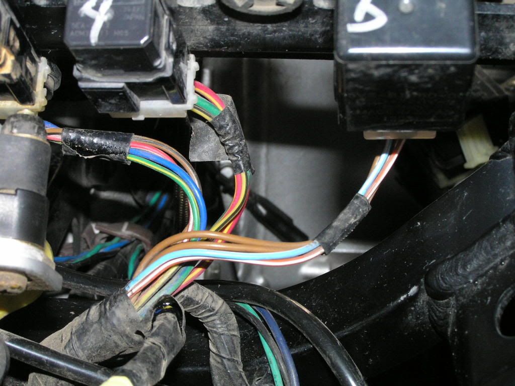
Relay #3 in my photo is the Radiator Fan Motor relay. All four wires match the SM wiring diagram as you can see in the below photo.

Relay #4 is Headlight Relay #1. Again, all four wires match SM wiring diagram colors.

Relay #5 - well, hell if I know. The Fuel Injection System relay is the only one left, but those wires aren't anywhere close to what the SM wiring diagram says (red, red/black, red/blue, and blue/yellow). In fact in my photo below it shows two brown wires, an orange/white wire, and a green/white wire. According to the SM wiring diagram an orange/white wire doesn't even exist, and nowhere do two brown wires go into a relay. So they got the diagram messed up to the actual wire colors. Still, it must be the Fuel Injection System relay. I *think* I verified that when I had it all apart trying to figure out which relay was which.

Photo of wiring going into relays 3-5 (as labeled in my photo above)

PB160042.jpg


Last edited by a moderator:
One of those relays could be the one which unlatches the glove box. It operates the electric solenoid latching mechanism.

This relay has a 4 wire connector.

Brown

Brown

Sky Blue/White

Orange/White

If you put the bike in gear, then turn on the ignition, then shift to neutral this relay should pull in.

I'd say the one on the far right is this glove box relay.

The 2003 will be different from the others since it doesn't have the glove box and relay.

 
The fuel injection system relay is under the seat. The starting circuit cut-off relay and the fuel injection relay are packaged together into one unit along with a bunch of diodes. This package is mounted next to the air pressure sensor under the seat.

The lineup in SkooterG's photo:

Starting at left

Hi/Lo Beam Headlight relay

Turn Signal Flasher relay

Radiator Fan relay

On/Off Headlight relay

Glove Box Latch relay

 
On the 2003 the fuel injection relay is up front with the other relays. On the '04 and '05 (maybe others) this relay was moved back under the seat.

'03 Fuel Injection Relay

Four wire connector

Red

Red/Black

Red/Blue

Blue/Yellow

 
One of those relays could be the one which unlatches the glove box. It operates the electric solenoid latching mechanism.
This relay has a 4 wire connector.

Brown

Brown

Sky Blue/White

Orange/White
Good find!

Where did you get that info? My 2004 service manual's wiring diagram doesn't show the glovebox wiring.

 
On the 2004 Supplementary Service Manual's wiring diagram the accessory box relay and solenoid (glove box) appear just to the left of the fuel pump in the middle of the diagram.

A troubleshooting guide for the Accessory Box System is included on pages 137 and 138 of this supplementary manual.

It never mentions where the relay is located and none of the included cable routing drawings show its location. But it would appear that it's the far right relay (viewed from the front) near the instrument cluster.

 
If you put a finger on the relay and then activate its circuit (say, hi/low beam) -- you may feel the relay operate?
I just tried it and that works! Definitively in the right side #1 (sitting on the bike) position.

Now to figure out which wire to tap into..... <_<

 
Last edited by a moderator:
What are you trying to accomplish? I'll help if I can.
Can't answer for anyone else on this topic, but maybe you can tell me...

I'd like for the low beams to stay ON when I activate the high beams. I know I can do it, and HOW to do it, with an additional relay installation for each headlight assy., but can it be done with the existing headlight relays?

And while you're helping, how about penciling out the "how-to" diagram?

(I don't ask for much, do I?)

 
Not sure if that's a good idea. The momentary pass switch on many bikes outside the U.S. powers the high beams directly bypassing the high/low beam relay.

So if you're using low beams and you press the pass switch both low and high beams are powered together until the pass switch is released.

The pass switch has no effect on low beams except they'll be less bright due to the additional voltage drop in the wiring.

Not sure having both beams on continuously is a good idea. May overheat something.

 
Top