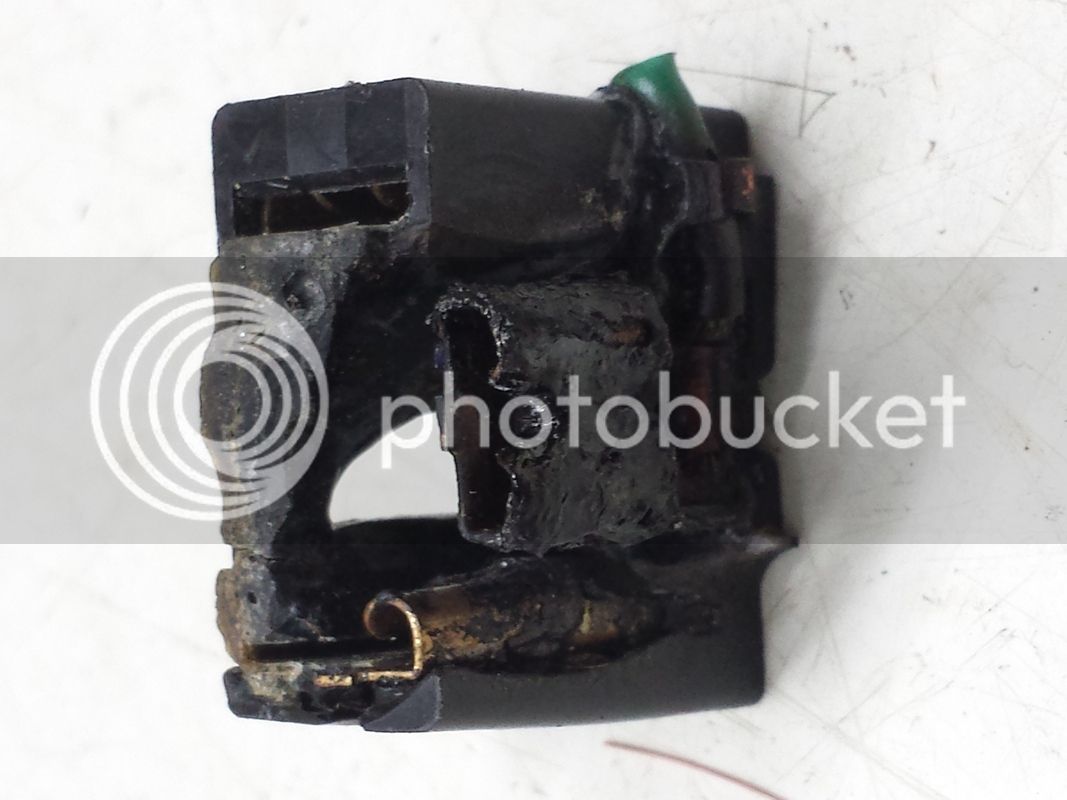
Toasted Headlight Socket

Yamaha FJR Motorcycle Forum

Help Support Yamaha FJR Motorcycle Forum:

This site may earn a commission from merchant affiliate links, including eBay, Amazon, and others.

RossKean

Well-known member
Joined
Feb 15, 2010
Messages
7,233
Reaction score
3,732
Location
Fredericton, NB
I changed both headlight bulbs about a month (and 10,000 miles) ago. I noticed, today, that my left headlight was out. Oh well, it was a cheap bulb so I just got another to replace it. It was a ***** getting the socket off the bulb and I noticed that the middle tab on the bulb looked burnt. Not good! So I looked at the socket and it is pretty much toasted. I am assuming that the bulb base overheated and cooked things.

Anyway, has this happened to anyone before and how did you fix it? Parts fiche only lists the complete sub-harness for $200+. I wonder if a standard H4 automotive socket is the same size as the Yamaha one? Obviously, the tabs line up with the H4 but I don't know about physical dimensions of the case. Do they come with wires to splice into the harness or are the wires crimped to the terminals? I am concerned that there may not be enough working room without pulling the nose off. I probably need to cut the wires back an inch or so since they are probably cooked and somewhat oxidized.

Crap!

 
Last edited by a moderator:
If the socket fits the bulb use it. The socket has no electrical properties other than to keep the contacts separate. That function apparently has failed in your system. Check your fuses for a fried one or any other short. That's what probably burnt out your bulb. Splice the wires anywhere you can, just make sure everything is thoroughly insulated...

Good luck

 
If the socket fits the bulb use it. The socket has no electrical properties other than to keep the contacts separate. That function apparently has failed in your system. Check your fuses for a fried one or any other short. That's what probably burnt out your bulb. Splice the wires anywhere you can, just make sure everything is thoroughly insulated... Good luck
I'm pretty sure that the problem was with the cheap bulb and/or some corrosion in the socket. In any case, the socket is cooked and needs replacement. The bulb filament is still intact but the solder joints to the tabs are melted. I think the fuses are still OK. High resistance connection and overheat; not a short (I think).

The only socket I can find at a local parts place is one with three leads designed to be spliced onto the existing wiring. These are only 18 gauge and the socket looks to be constructed cheaply - what do you expect for $2.50? I would prefer to find a socket where I could crimp the cleaned up wires directly to the socket clips. Failing that, I would prefer to have 16 gauge or better wire. Not the cost, but the time to order and receive something better would mess up some plans.

 
If it were me I would do as you say and cut the wires back to good clean copper. Then using in-line crimps install a new headlight socket. I would look for a H4 connector with wires already attached.

I would definitely not use the old socket, the connectors will have been heat affected and will fail again.

The most likely reason for the failure was a (slightly) poor connection most likely on the dipped beam (on most of the time). It doesn't take a lot of resistance to generate a lot of localised heat.

 
If it were me I would do as you say and cut the wires back to good clean copper. Then using in-line crimps install a new headlight socket. I would look for a H4 connector with wires already attached.
I would definitely not use the old socket, the connectors will have been heat affected and will fail again.

The most likely reason for the failure was a (slightly) poor connection most likely on the dipped beam (on most of the time). It doesn't take a lot of resistance to generate a lot of localised heat.
There is no doubt that I will replace the socket. Just trying to find one that is better than the really cheap one I bought. Why didn't they spend an extra $0.05 to put 14 or 16 gauge wire on it? The grippers do not appear to be particularly robust either. I'll use it if I can't find something else. Will try the local Napa store when they open tomorrow AM. I will probably solder and heat shrink to insulate rather than using in-line crimps. As I mentioned, my preference would be to find a socket that could be dismantled so I could crimp the wires directly to the female connectors and then assemble the socket.

Edit: I saw some nice ceramic sockets on-line. I doubt that I will be able to find any locally and am not willing to wait a week or more.

 
Last edited by a moderator:
With a good safety factor, can I expect 18 gauge wire to have enough over capacity to carry ~6 amperes of current in continuous service without future problems? We should assume I can do a reasonably competent job of soldering (if I have enough room to work) so the joint is not the weak link. I might end out pulling the nose off the bike so I can get to it properly.

Looking at tables on the 'net, I see a pretty large variety of "safe" ampere ratings. Depends a lot on whether there is free air flow around the wire, the length of the wire, the number of conductors (vs. solid core) and how much voltage drop (and heat) one is willing to accept. I don't want to fix this twice so am I OK with the 18 ga. or should I hold off until I can get 16 or better?

 
Ross, I would look for "used" parts on Ebay or Amazon? You might get lucky and get the connector stripped out of a damaged written off FJR? I was helping a friend do his valve check and I broke a connection on one of his injectors! I was able to get that part of the harness for not too much and the problem is solved! Just a possibility?

Mark

 
Last edited by a moderator:
Ross - if you are not planning to solder the connection, consider my method for the conection.

(I hope I can type this explanation correctly)

I take the correct size butt splice solderless connector, and I use a dremel tool with a cut-off wheel to cut away just the plastic insulator. Then I use my crimping tool to crimp the metal splice on the bare wires, taking care to strip enough wire on each end, but ensure that the entire stripped portion is shoved into the connector. I find the shrink wrap provides far more waterproofness and some strain relief for the moving (vibrating) wires. I've had tremendous luck with this method for all of my bike accessory circuits (and many of my saltwater boat circuits too).

If you are going with a larger size wire for your new connector, consider the fact that too great a difference in size will make the splice connector challenging (this is not an issue if you are soldering the wires).

Hope this makes sense.

 
Last edited by a moderator:
With a good safety factor, can I expect 18 gauge wire to have enough over capacity to carry ~6 amperes of current in continuous service without future problems? We should assume I can do a reasonably competent job of soldering (if I have enough room to work) so the joint is not the weak link. I might end out pulling the nose off the bike so I can get to it properly.
Looking at tables on the 'net, I see a pretty large variety of "safe" ampere ratings. Depends a lot on whether there is free air flow around the wire, the length of the wire, the number of conductors (vs. solid core) and how much voltage drop (and heat) one is willing to accept. I don't want to fix this twice so am I OK with the 18 ga. or should I hold off until I can get 16 or better?
Have a look at this chart 18g wire is more than adequate for your needs. However, I would be much more concerned about the quality of the connectors. If they don't 'grip' properly you will have a re-run of your original problem!

As for soldering I would definitely not be doing that. Solder is OK on a PCB (or something like that) but definitely not good where it will be exposed to constant vibration. If you are determined to use solder, have a look here

 
Ross, I would look for "used" parts on Ebay or Amazon? You might get lucky and get the connector stripped out of a damaged written off FJR? I was helping a friend do his valve check and I broke a connection on one of his injectors! I was able to get that part of the harness for not too much and the problem is solved! Just a possibility?Mark
I have no problem with "used" parts if they are in good condition but there is no need to replace the whole harness and I want to fix it TODAY; not a week or more waiting for parts.

This looks good and not cheap i think..Also the seller has very good reviews 99,9 positive feedback from what i see.

https://www.ebay.com/itm/2-NEW-H4-Female-Headlight-Wire-Harness-Connector-Wiring-plug-socket-/181615206746?hash=item2a491c215a&vxp=mtr#shpCntId
I could order the parts from a lot of on-line vendors but this is not a quick solution. There are a number of vendors selling high quality ceramic-bodied H4 sockets.

'Pants - I have some non-insulated butt splice connectors that I would use if I go that route. I wouldn't go to a wire gauge that is heavier than OEM.

Have a look at this chart 18g wire is more than adequate for your needs. However, I would be much more concerned about the quality of the connectors. If they don't 'grip' properly you will have a re-run of your original problem!

As for soldering I would definitely not be doing that. Solder is OK on a PCB (or something like that) but definitely not good where it will be exposed to constant vibration. If you are determined to use solder, have a look here
I saw that particular chart plus a number of others with varying opinions on wire capacities. I think they all suggested that 18 ga. could carry 6 amps but I would prefer to overdo it than be marginal. There is no point in exceeding the wire size used by Yamaha; it could just move the point of failure up the line. (Anyone know what the stock wire size might be?) I agree that the weak link is likely the socket connectors themselves and for this reason, I would like to find a better socket. Regarding the use of soldered connections in a high-vibration environment - I have made soldered connections on bikes without issue in the past and have never had a problem. I make sure that the joint is well-filled with solder and make sure there is minimal strain and the joint is well immobilized with heat shrink. I try to do something like the photo in the NASA link you provided. One of the problems is getting enough good wire on the bike side to be able to make a good joint. The burn is worst on the ground side and I may have to cut off an inch or more to reach good (un-oxidized) copper. Much easier if I take most of the plastics off.

Has anyone had a toasted headlight socket on an FJR or am I unique?
The chart shows that 18g wire is good for 16Amps..........

If it is just the ground wire that needs to be shortened, then consider installing a 'temporary' new ground (until you remove the tupperware for another job).

 
Wire gauge isn't what determines the current carrying capacity by itself. The tables are based on the temperature rise of the wire caused by the current flow through the wire. There are 'free air' tables and raceway tables based on the ventilation around the wire. The area around the headlight is pretty well open and should allow the wire to shed heat. If a high current wire were run in an enclosed space or in a tightly packed harness then using a bigger gauge wire would have some benefits.

If the wire isn't burned to a dull copper color, if you have soldering skills and if you dress the wires properly before soldering IMO there is nothing wrong with soldering. I would personally solder before crimping. If you are going to crimp, please use a tool that makes a crimp which is selected for the type of connector being used and for the correct gauge wire.

I have now seen and heard of a number of burned headlight sockets. It always happens after a bulb replacement, I've never heard of an OEM bulb burning a socket. I have changed a number of bulbs in my FJR and other FJRs and AFAIK, I haven't burned up a socket yet. Next time I have the displeasure of the job, I'll look at the socket and see if the bulb post can fit between the blades in the socket and the housing without going into the socket terminals.

 
Wire gauge isn't what determines the current carrying capacity by itself. The tables are based on the temperature rise of the wire caused by the current flow through the wire. There are 'free air' tables and raceway tables based on the ventilation around the wire. The area around the headlight is pretty well open and should allow the wire to shed heat. If a high current wire were run in an enclosed space or in a tightly packed harness then using a bigger gauge wire would have some benefits.
If the wire isn't burned to a dull copper color, if you have soldering skills and if you dress the wires properly before soldering IMO there is nothing wrong with soldering. I would personally solder before crimping. If you are going to crimp, please use a tool that makes a crimp which is selected for the type of connector being used and for the correct gauge wire.

I have now seen and heard of a number of burned headlight sockets. It always happens after a bulb replacement, I've never heard of an OEM bulb burning a socket. I have changed a number of bulbs in my FJR and other FJRs and AFAIK, I haven't burned up a socket yet. Next time I have the displeasure of the job, I'll look at the socket and see if the bulb post can fit between the blades in the socket and the housing without going into the socket terminals.

The figure I quoted came under the heading "Maximum amps for chassis wiring".

From the notes above the table :

Load Carrying Capacities (see table below)

The following chart is a guideline of ampacity or copper wire current carrying capacity following the Handbook of Electronic Tables and Formulas for American Wire Gauge. As you might guess, the rated ampacities are just a rule of thumb. In careful engineering the voltage drop, insulation temperature limit, thickness, thermal conductivity, and air convection and temperature should all be taken into account. The Maximum Amps for Power Transmission uses the 700 circular mils per amp rule, which is very very conservative. The Maximum Amps for Chassis Wiring is also a conservative rating, but is meant for wiring in air, and not in a bundle. For short lengths of wire, such as is used in battery packs you should trade off the resistance and load with size, weight, and flexibility. NOTE: For installations that need to conform to the National Electrical Code, you must use their guidelines. Contact your local electrician to find out what is legal!

It all seemed fairly clear to me..............


Last edited by a moderator:
It was OK for a month after I replaced the headlight and a total of around 10,000 miles so I wouldn't say it happened right after installing the new bulb, at least in terms of hours of use. Looking at the socket, I'm surprised that it didn't set fire to something!

Anyway, it is fixed now but I will keep a close eye on it. I trimmed back the leads a bit before soldering but couldn't go far because of a lack of wire length. I probably should have taken all of the plastic off and brought it back to the harness. Next time if this doesn't hold up!


Last edited by a moderator:
Thanks for the picture. This sort of problem starts off with just a very slight resistance, there is some heat generated, this heat affects the contact tension and the resistance increases slightly and on it goes until you end up with a mess like you had. The heat generated is a function of current (Amps) squared times the resistance (Ohms). Some people scoff at the apparent low wattage initially until you ask them to hold a low wattage bulb for a few seconds!.......

Sounds like you have made a good job of it and hopefully you will never have to worry about it again.

 
Eastern Beaver mark a real good bypass harness for the FJR.

So long as the other H4 socket is good, ya good to go and it will reduce the load from the neutral spider connector circuit.

Just terminate the crook wiring on the burnt loom.

 
Last edited by a moderator:
Would using di-electric grease on the connection help mitigate against this happening?
I don't know. Maybe, if the initial cause was corrosion due to moisture ingress. I think the more likely cause was a connector that was a bit loose. A little arcing, some oxidation, increased resistance and then snowball (or fireball) from there. Once a little heating starts, it progresses rapidly.

 
Top