Moving my cruise control servo

Yamaha FJR Motorcycle Forum

Help Support Yamaha FJR Motorcycle Forum:

This site may earn a commission from merchant affiliate links, including eBay, Amazon, and others.

FJR-Richie

Well-known member
Joined
Feb 8, 2006
Messages
116
Reaction score
1
Location
IBA #28671
Having seen what Ionbeam and others have done in terms of mounting their Audiovox CC servos on ABS bikes near the rear tire, I decided to relocate mine from under my seat. So far it has been a nightmare.

First I decided that since I had the fuel tank off and unhooked my throttle connection that it would be a good idea to replace the screw I had partially stripped from the origin instal on my fuel rail. Bad idea - fully stripped it and then spent the next two hours drilling it out. Fine.

Next day decided to paint the servo bracket and spray can exploded on me. Great, black paint everywhere - thankfully not anywhere near my bike.

Finally get cleaned up, bracket painted, now its time to mount. I remove one of the bolts from the left rear bag mount to fasten the bracket to. Mount the servo, everything looks good, put bag back on and check clearance with tire - no clearance! Try several different configurations and still not happy with the clearance.

Finally get to the point where I think I will have adquate clearance and bam - stripped threads in the rear bag mount. Now I am going to need to drill and retap that hole. This f'ing sucks. :angry:

BTW - for those of you who have successfully mounted this way - how much clearance do you have between your servo unit and the rear tire - if anyone has any pics I would much appreciate it.

Rich

 
Finished moving my servo - have about 1/2" clearance from tire which seems to be more than adequate. Also changed my vaccuum canister to the NAPA fuel filter and mounted in between tool tray and gas tank - works great.

 
Last edited by a moderator:
Finished moving my servo - have about 1/2" clearance from tire which seems to be more than adequate. Also changed my vaccuum canister to the NAPA fuel filter and mounted in between tool tray and gas tank - works great.

Okay-

I am stupid and scared as i am about to embark upon this project myself. Question: why does the servo motor not fit with Abs? in the farkle they have it mounted on the right side of the bike. Could it go on the left? What about under the seat somewhere (not having looked yet myself?)

Do you have any pics of what you did?

 
Okay-I am stupid and scared as i am about to embark upon this project myself. Question: why does the servo motor not fit with Abs? in the farkle they have it mounted on the right side of the bike. Could it go on the left? What about under the seat somewhere (not having looked yet myself?)

Do you have any pics of what you did?
Q#1-The ABS valve body and motor take up the space used by the installer in the non-ABS install.

Q#2-No room on the left, air cleaner housing, ECM and plug take all avail space. It does fit under the seat, as well as the fuel filter accumulator, quite nicely-but takes up all available space. Note-if you have a Corbin seat, some tray mods over and above the front notch cut for the servo nose will be necessary, as discovered this weekend during another install, due to clearance issues.

flien-having read numerous posts from you with questions, and honest qualms about this install, I would suggest you not attempt this on your own-while straightforward in most aspects, there are several procedures that are not for the mechanically disinclined, and could result in real problems if done incorrectly. If unable to secure the help, physically, of someone who has done one, I would find a shop willing to do it. Or, live with a vista-cruise or the like until you can find someone to help.

 
Thanks for your honesty and help. I feel that I am a pretty good wrench. I know that I can do this project, but 1 thing I hate to do is anything half-assed. By asking these questions I have found tons of info from folks like you that have done this before ie. I did not know that the module did not fit on the right side as show in the farkel. If I did not know this, I would have torn in to this thing and been complete stumped as to how the author did it. My first goal is to have a clean look to my bike with as few "mirror mount" modifications (if you will) as possible. I also want to "do no harm" and be able to return to stock if need be.

and finally, spend as little time in the garage engineering as possible. Due to my current situation, none of my tools are available to be. I will need to use a buddies garage, and not have my bike camp there too long. I hope this makes sense.

Finally, it can be difficult to visualize just what has been done from just text alone. If you have any pics of your mounting that you would care to share I would truly appreciate it!!

Thanks in advance!

 
[Pre-Edit -- FU Photobucket, to view the photos you will need to install one of these addons Firefox fix Chrome fix ]

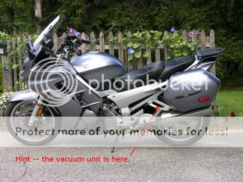
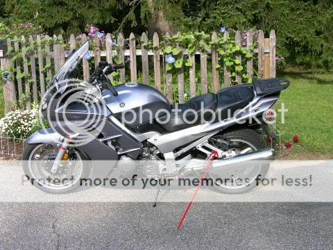
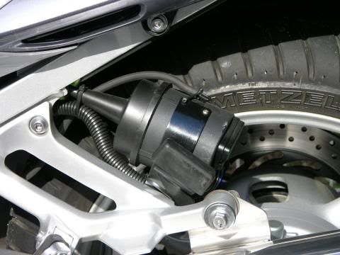
Here is one way to install the AVCC on an ABS FJR. The mounting bracket had to be modified to get it to fit as shown.

bags_sm.jpg


nobags_sm.jpg


vac_sm.jpg


Last edited by a moderator:
Here is one way to install the AVCC on an ABS FJR. The mounting bracket had to be modified to get it to fit as shown.
bags_sm.jpg


nobags_sm.jpg


vac_sm.jpg

Nice Job-

what about weather, rocks, or a passenger? Do you think those would be any factor with this install? I am also wondering what lies behind the fairing and it there would be a spot to locate this there?

 
Nice Job-
what about weather, rocks, or a passenger? Do you think those would be any factor with this install? I am also wondering what lies behind the fairing and it there would be a spot to locate this there?
The servo sits inside the frame, so it shouldn't be in the way of a passenger. If they're sticking body parts in there, they're going to have bigger problems than dislodging your CC. Ionbeam mentioned he had done a LOT of riding in the rain with no problems. The cannister itself seems fairly durable, so I'd guess it's a safe bet behind the saddlebag (that's where I put mine, and it's been fine).

The fairing is surprisingly tight to the guts. Very little room for anything.

Jeff

 
My only other question would be the Part number for the Fuel Filter? Assuming this is just a standard filter, I am guessing that you just use a rubber plug on 1 end?

 
Here is one way to install the AVCC on an ABS FJR. The mounting bracket had to be modified to get it to fit as shown.

bags_sm.jpg


nobags_sm.jpg


vac_sm.jpg

Nice Job-

what about weather, rocks, or a passenger? Do you think those would be any factor with this install? I am also wondering what lies behind the fairing and it there would be a spot to locate this there?
I too borrowed uh copied this setup from Ionbeam. I ride extensively with a passanger and so far through rain/snow/sun it is working perfect.

The only slight variation on this is that my canister is rotated different, but still almost identical to whats in the photo's.

 
My '04 now has >22k miles with the cruise installed. It has seen highway, construction, miles and miles of dirt roads, fire access roads and um, some places in Maine where I'm not sure it was ever a road of any kind. It has been well washed in rain but hasn't seen much snow :eek: In addition to sealing the control pad (primeter and key openings) I sealed the wire entrance to the servo unit -- it will be obvious once the wires are installed. The front part is just the rubber diaphragm and is very weather resistant. I took the sucker apart to check for the at risk places. THE KEY PAD MUST BE SEALED. Someplace in this forum is a description of how to do that.

For the fuel filter, go to any Honda parts supplier and ask for an '85 Goldwing filter. There are lots and lots of other automotive fuel filters of reasonable size at auto parts stores. The filter goes anyplace in the hose, after the vacuum check valves and before the servo. The fuel filter simply goes in series with the line -- no Tee -- just as if it were a gas line. If the fuel filter has an arrow (flow direction) the arrow should point to the throttle bodies. Search for Pepperell and filter, he has used an auto type fuel filter.

The only place in the faring where there is perhaps room is behind the chin faring, next to the headers. I believe that to be one Hell of a bad place :lol:

 
Well i picked up the CC today, and have the mount orderd from Skyway. I was playing with it as much as I could with out tearing into the bike. I think for me, I will mount under the seat. On all the bikes I have had, I have never used that area for any kind of storage. I will recess the plastic a little bit where the cable with run out so that it was a nice smooth corner. I will also play with the mounting brack to check for best fit. I think I will mount the canister close once I figure the engineering out.

 
Dont hate me!! But....I have another question: I just noticed this in the farkle.

"Connect the Red wire to the Brown wire at the brown plug and connect the Purple wire to the Yellow wire at the brown plug. "

What "brown plug" are they referring to? are they referring to the wiring harness that plugs into the back of the Servo unit? If so, my plug is white and that would answer a lot of questions. furthermore earlier in the instructions he states:

"Now find the large wiring harness and attach it to the keyed 10-pin connector. Lay the wires flat before replacing the plastic cover which will weatherproof the switch pack and harness connection."

I assumed that you put the cover on at this point. Perhaps not?

So if you are to connect the red wire on what looks to be a second (bottom pin) Do I just simply pull the red wire out and move it over to the bottom pin? I ask because I was tugging on the red wire and it doesnt seem to want to pull out. I figure I would ask before I broke anything.

Question 2:

This maybe a bit anal, but if you look at the picture of the Servo module under "wiring" you will see a pic of it mounted on the right side of the bike. I noticed the 90 deg connector not supplied in the kit, and the 2 to 1 pvc diode connector. I have search several local parts store and cannot seem to find a diode like that one. Any ideas?

Thank you in advance!

 
[Pre-Edit -- FU Photobucket, to view the photos you will need to install one of these addons Firefox fix Chrome fix ]

QUOTE
I have another question:
Hmm, I count more that one question...

QUOTE
"Connect the Red wire to the Brown wire at the brown plug and connect the Purple wire to the Yellow wire at the brown plug. " What "brown plug" are they referring to? are they referring to the wiring harness that plugs into the back of the Servo unit? If so, my plug is white and that would answer a lot of questions.
The Brown plug they are referring to is part of the FJR wiring harness. When you remove the right side plastic at the ABS unit you will see the brown connector they are referring to. The Brown and Yellow wires are the FJR harness colors.

QUOTE
"find the large wiring harness and attach it to the keyed 10-pin connector. Lay the wires flat before replacing the plastic cover which will weatherproof the switch pack and harness connection."
I assumed that you put the cover on at this point. Perhaps not?
You put the cover on at this point.

QUOTE
So if you are to connect the red wire on what looks to be a second (bottom pin) Do I just simply pull the red wire out and move it over to the bottom pin? I ask because I was tugging on the red wire and it doesn’t seem to want to pull out. I figure I would ask before I broke anything.
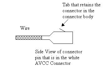
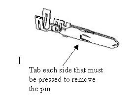
It's been a couple of years since I did my install and I don't recall why this is necessary. However, if you need to pull a pin out of the AVCC white connector at the steering head the following picture may help understand what you need to do. There is a small springy tab on the top of the brass connector that locks the brass connector into the white housing. From the connection end of the housing you will need to slip something in to press down on the tab and the connector will pull out. Be sure the tab is lifted up before pushing the connector back in.

AVCCPin.jpg


EDIT: I just realized that the white AVCC connector may may use round Molex type pins, in this case the pin will look like this:

Molex2.jpg


QUOTE
I noticed the 90 deg connector not supplied in the kit
90 Deg connector? Are you referring to the vacuum hose connector? If so, it is an easy find at an auto parts store.

QUOTE
and the 2 to 1 pvc diode connector. I have search several local parts store and cannot seem to find a diode like that one. Any ideas?
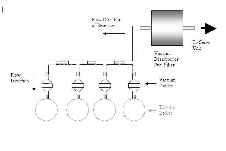
The 3 connection vacuum diode was used to facilitate a Tee connection for the vacuum canister. I used standard 2 connection vacuum diodes and located my vacuum reservoir ‘in series’ rather than as a Tee. You will note that the install you are looking at uses only 1 vacuum diode just before the servo unit.I would strongly recommend that you use a diode on each throttle body that you connect to. I used 3 Tee connectors and 1 90 deg connector to plumb the throttle bodies.

AVCCThrottleBodyConnections.jpg


Unsolicited suggestions
smile.gif
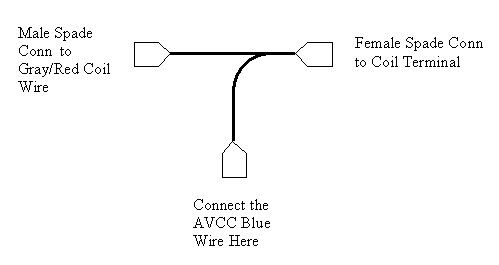
Where ever possible I try to refrain from using wire taps. Here is a Tee connector I made to tie into the coil. The coil is real important to me so I didn't want to compromise the integrity of the wires.

CoilTee.jpg


Hope I understood some of your problems, hope some of this makes sense.

 
Last edited by a moderator:
So if you are to connect the red wire on what looks to be a second (bottom pin) Do I just simply pull the red wire out and move it over to the bottom pin? I ask because I was tugging on the red wire and it doesn’t seem to want to pull out. I figure I would ask before I broke anything.
Ok- I understand now, the RED and PURPLE wires come out of the Servo unit, and plug in the respective wires mentioned on the FJR's Brown Wiring Harness. NO NEED TO MOVE WIRES ON SERVO UNIT! (We have comprehension!!)

AVCCThrottleBodyConnections.jpg


I See here that you connected the mutiple ports to the throttle bodies. Only 1 connection is needed correct? you must done this for redundancy measures? Or did you feel that 1 vaccum connection was not enough?

Unsolicited suggestions :) Where ever possible I try to refrain from using wire taps. Here is a Tee connector I made to tie into the coil. The coil is real important to me so I didn't want to compromise the integrity of the wires.
CoilTee.jpg
Here is a point of confusing for me. It is my understanding that the Blue wire connects to the Grey/Red connector on the coil Period. You are showing a female spade connector going to the other side of the coil? In other words, they are all connected together? Or is the "Female Spade Conn to Coil Terminal" something else?

BTW- I cannot express to you how much I appreciate you taking your time to explain this to me. This is an awesome site and guys like you make it that way. I now have a very clear picture in my head of what to do aside from the above. So now instead of looking at the web posts, going back to the bike, and going back to the web posts Wondering if I am doing things right, I will now be able to remove the tank, seat, covers ect. and just get to work!

 
Unsolicited suggestions :) Where ever possible I try to refrain from using wire taps. Here is a Tee connector I made to tie into the coil. The coil is real important to me so I didn't want to compromise the integrity of the wires.
CoilTee.jpg
Here is a point of confusing for me. It is my understanding that the Blue wire connects to the Grey/Red connector on the coil Period. You are showing a female spade connector going to the other side of the coil? In other words, they are all connected together? Or is the "Female Spade Conn to Coil Terminal" something else?
This is illustrating a way to wire in the CC unit without using wiretaps. It's a 3 way wire connector, so the left side (male spade) connects to the female plug on the gray/red wire that was pulled off of the coil. The right side (female spade) is the "new" connection to the coil terminal. The bottom connector is where the CC hooks to the wiring to get the signal from the coil.

FWIW, I used wire taps, and I did have trouble with two of them where they didn't cut through the insulation on the wire and get a good connection, but it was easily corrected.

Hope that helps.

Jeff

 
See here that you connected the mutiple ports to the throttle bodies. Only 1 connection is needed correct? you must done this for redundancy measures? Or did you feel that 1 vaccum connection was not enough?
From another thread about the AVCC Who here has installed Cruise Control:

<snip>

1. The 'vent tube' is the vacuum supply to the vacuum servo of the AVCC, it is what moves the diaphragm that pulls the throttle linkage. One end connects to 1 or more of the vacuum port nipples that are used for synching the throttle bodies; to a vacuum reservoir if used; then to the servo unit. It has been a topic of much discussion as to how many ports should be used and if a vacuum reservoir is necessary. Every port you use should have a vacuum check valve (vacuum diode). You can't make a wrong choice here. My results, in my application, shows that using 4 ports (4 check valves) and a small reservoir (Honda Goldwing fuel filter) works best for me. Others have been just as satisfied with their results using fewer ports and some having no reservoir either. A topic search should show why people choose different setups.

</snip>

I find that 4 ports with a reservoir gives faster speed setting, reduces abrupt throttle changes and reduces speed sag when I have a pillion and a full load. Most notably reduces speed sag with afore mentioned load on steep mountain roads.

Here is a point of confusing for me. It is my understanding that the Blue wire connects to the Grey/Red connector on the coil Period.
In the end, my little Tee will have the coil, Gray/Red wire and Blue wire all connected together. The reason I suggest the Tee is because it lets you plug all the wires together rather than splicing them. This is suggested when connecting to the coil for reliability. You can use the blue 3M Scotch Lock taco connector to connect the wires and it will do the same thing as my Tee. Only difference is the taco will have cut wire insulation and perhaps wire strands. Your choice. I make and use Tees where I can and avoid cutting insulation and wires. I forgot to mention that I use heat shrink sleeve to cover the Tee connectors when done. Holds 'em together and insulates the joints. Find shrink sleeve at Radio ****, err Radio Shack, auto parts, hardware stores, etc.

 
Last edited by a moderator:
Thanks Guys!! I am all Dialed in Now!! Just waiting on the part to come it now.

:clapping:


Latest posts

Top