Brodie
Darksider #16 - and Proud of it !
Tim
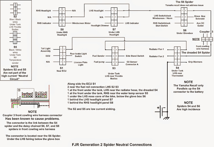
There are 6 grounding shunts on this bike that you need to locate and inspect for yourself. There is also a connector between the main harness and the forward sub harness which serves the faring forward of the frame. All 6 grounding shunts have black wires leading out of them. There are 2 other shunts which are not part of the grounding buss, one will have a black with whit stripe wire, the other will have black with blue strip wire.
Years ago when this first came to light, one of our forum members made a spreadsheet and labeled them in the following order...
#1 is located behind the left side panel under the seat, beneath the air box cover.
#2 and #3 are located under the fuel tank, to the left along side the frame next to where the fuel line plugs into the throttle body fuel injector rail. one of these has striped wires and are part of the low voltage electronics.
#4 is located under the fuel tank, to the left and forward of the cylinder head. This grounding shunt (spider) is the one that has the most reports of failure. This is the one that the Yamaha Recall Harness ties into; it's other end ties back into the main grounding wire at a large connector beneath the lower right fairing, in front of the battery.
#5 is located under the fuel tank, to the right and forward of the cylinder head. This one is the other striped wire, low voltage electronics shunt.
#6 is located down low in the left forward fairing near the left horn, in front of the accessory box. Gain access to this by removing the black inner panel next to the horn.
#7 is located just to the right and above the left headlight socket. Gain access to it by removing the left black upper dash panel.
#8 is located just to the left and above the right headlight socket. Gain access to it by removing the right black upper dash panel.
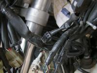
The other connector which sometimes gives grief is located beneath the left dash to the rear of the coolant filler cap. The easiest access is to remove the left lower faring panel. There are several large connectors in this area, find the sub harness and let it lead you to the proper one.
The ground shunt (spider) that your dealer most likely serviced was #4. These grounding shunts are daisy chained to this one shunt, as well as two other components. It's sixth wire leads from this, connecting the daisy chain back to the main ground wire deep within the wire harness; the main ground heavy wire leads from the voltage regulator to the battery negative terminal.
We have found that when the bike is factory fresh, the connector pins are clean and corrosion free. Given a year or three just having them exposed to the atmosphere will allow them to oxidize to the point of creating resistance. When there is electrical resistance you get heat, the more heat the more resistance you get. It will eventually become a thermal runaway and you will get scorching of the connector, annealing of the pin metal and worse case, melting of the wire insulation leading back into the main harness.
Since you retrieved the bike from the dealer service department, your job is to gain access to all these connectors to look for a burned pin. If/when you find it, you have a decision to make...
Take it back to the dealer service department for them to replace the whole wiring harness with a new, re-engineered one. This is also covered in the recall, if there is damage, it will be covered on Yamaha's dime.
Or
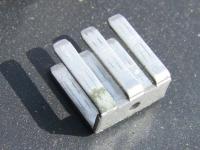
Fix it yourself. If the pin isn't too far damaged, you may have luck removing the black cap and re-inserting the shorting bar several times. The sliding contact action will self clean the oxidation from these pins. You should do that for ALL the connectors on the bike, and coat them with an anti-corrosion spray like CorrosionX or ACF 50, or inject a bit of Permatex dielectric grease into the female side of the connector. The idea is to break the corrosion and create a barrier from the oxygen in the air thereby inhibiting it's regrowth.
IF the pins are too far damaged, the easiest way is to remove the plastic connector from these pins, cut them off leaving the wires as long as possible, twist them together, insert them into a butt splice and crimp/solder them together. Then cover with tape or heat shrink.
Please note that when I designed my Grounding Harness, it was meant to prevent damage from occurring, not to fix an already damaged grounding shunt.
These are great machines, but they're designed and built by humans. The neat thing is that there are owners forums like this which bring together smart people who will share their ideas and experiences, and help each other out.
Good luck, I hope this helps.
Brodie
Last edited by a moderator:


