drilling small holes in the clutch basket?

Yamaha FJR Motorcycle Forum

Help Support Yamaha FJR Motorcycle Forum:

This site may earn a commission from merchant affiliate links, including eBay, Amazon, and others.
My Yam FSM clearly shows the transmission main-shaft is supplied oil with several holes to feed the transmission gears and clutch-basket needle bearing. This would indeed bathe the entire push-rod assembly in oil within the main-shaft. It seems logical the O-ring on the last component of the clutch push-rod assembly is there to stop the flow of oil (despite the fact that it is essentially the stopping point for additional oil getting inside the clutch-pack). I’d speculate the actual pressure and volume is relatively low for the main-shaft and with so many “exit” holes, there is zero chance that it could ever counteract the force of the of clutch pack’s diaphragm spring.

Mr. BR


Oh come on now! It's just a healthy discussion about the merits of a single O-ring!

Seeing how much discussion there has been on clutch soaking, I think this offers a real possibility of getting some additional oil to the clutch which could reduce/eliminate the need for additional soaks and perhaps improve clutch function. Anyway, I've been wrenching on my own bikes for 30 plus years and I'm genuinely surprised by how dry and dirty some owners have found their clutches (that's a WET clutch??). I don't post much but I do try to be helpful when I can. I've never had a new bike and my '05 is the newest I've ever owned!

Mr. BR

 
Looking at these photos it appears that plenty of oil gets into the clutch boss and lubes the pressure plate bearing.

https://atrophy.lock.net/pi/20100320/DSCF5879.jpg

https://atrophy.lock.net/pi/20100320/DSCF5878.jpg

You can see two large holes in the back of the clutch boss at approximately 12 and 6 o'clock in this photo where oil enters the boss.

https://atrophy.lock.net/pi/20100320/DSCF5899.jpg

One might believe there's no shortage of oil here. The problem is getting the oil from this location to the outside of the boss and onto the steel plates.

From my experience on the '04 FJR the operation of the clutch has never been an issue. Sure, it bangs in going from neutral to 1st when you're sitting still but that's easily understood and appears not to be a problem. Otherwise it shifts fine. I always select 1st gear before I start the engine to avoid the bang.

The quality of shifts on a bike is determined to a great extent by the skill of the rider. Motorcycle transmissions are crude and unforgiving.

 
What's actually behind that two holes? why do u think oil come from there? everyone have his theory :)

 
I found that when I switched to Rotella T6 Synthetic lubricant that it made shifting much quieter and smoother. I resolve the 1st gear clunk by disengaging and engaging the clutch several times during the 1 - 2 minutes it takes to back out of my garage and make a final check of turn signals, mirrors, jacket zippers and helmet strap. Cycling the clutch several times ( 5 - 6 times ) normally results in a quiet Netrual to 1st gear shift. When temperatures are close to 40 F or 5 Centigrade I will cycle the clutch a few more times.
+1 to this, and I will blip the throttle with the clutch in a couple of times which should aid in the plates freeing up. No more 1st gear clunk. Works on many other wet clutch bikes too. I have suggested it to many riders that I see clunking into first. I ran the fjr at idle with the clutch cover off once, after watching a video of some one doing this. There is just not much oil getting to this clutch guys. Looks like incidental slinging is all it gets. Ill never go away from Rotella T6.

 
RossKean said...
It just isn't that big of a problem!! A few people have needed a clutch clean and soak. Very few have needed more than one. My clutch is working very well after many miles.

I wouldn't consider messing with something that really doesn't need to be fixed. (Unless, of course, you are an expert automotive engineer with specific experience with hydrodynamics related to oil flow and intimate knowledge of the workings and requirements of mechanical wet clutches.)

Its Friday!!!

Well, it's Monday, but I started it Friday
tonguesmiley.gif


I ain't no edumacated, high falut'n expert at this, but...

I decided to have a good look at my clutch assembly on my '08 Advanced Edition. Granted, it was working just fine, however, this thread got me thinking how it could be improved so the 'Clutch Soak' would be a thing of the past. The suggestion for adding extra holes in the hub to let increased amount of oil flow onto the steel and friction discs sounded good to me. I had done that very same thing to my Honda Ascot many years back and it seemed to improve it's performance/feel IIRC, and since it's relatively easy to get to, and I had an extra cover gasket, I had a look.

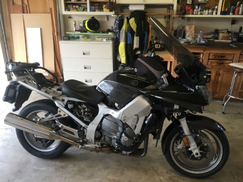
To make things easy, I decided to remove the bodywork so I could also check up on other things while I was at it.

b0b8e2e1-3693-490b-ba05-9e3fd517071a_zpsjrc6tqmc.jpg


The bike was still warm from a 20 minute commute earlier that morning.

c61ea25f-e778-419b-b53c-74fcf085aa21_zpsg0xveoby.jpg


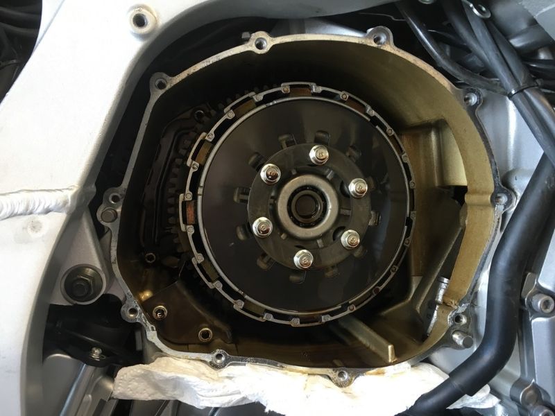
Notice the big hole to the right of the clutch assembly where the crankshaft throw is. Murphy lives down there and is hungry for one of those small cap screws that I was about to extract. Needless to say I covered it before I even started. Off came the pressure plate and the friction elements one by one. I just stacked them on top of each other in order of extraction. I wanted to do a oil coating upon reassembly, not an overnight oil soaking.

As you can see, there was plenty of oil in the clutch hub area. I don't think it's oil starved, I'll go into that in a bit.

f186aa4c-0b57-4354-bc93-abea36499020_zpsrghnxivb.jpg


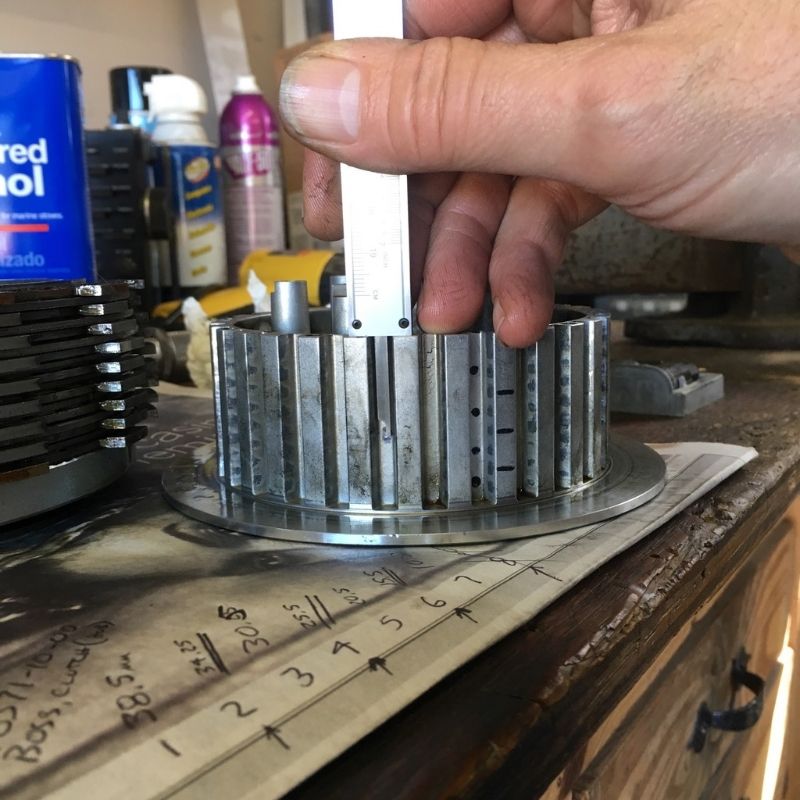
I found that there are 4 holes, 3mm diameter servicing the clutch plates. You can see them in the above picture at the 3

o'clock, 5 o'clock, 9 o'clock, and 11 o'clock positions.

When I plotted them out in one of the ribs on the outside diameter, I could see by the witness marks that every other steel plate had a oil hole above it. In the picture below the bottom black dot is actually one of the oil holes Yamaha gives us. The other 3 black dots are the positions of the other 3 oil holes distributed about the perimeter. I decided to add 3 more holes of the same diameter, also distributed about the perimeter. The lines on the rib in the picture below represent the levels I drilled them at. I chose not to drill a 4th hole near the edge of the hub for fear of weakening the die casting. By adding these holes, now 7 of the 8 steel plates has it's own oil hole to service it. I figured the 8h plate and pressure plate, being on the outside of the stack up has a good chance of getting splash from the #4 cylinder crankshaft throw.

9b442f9d-6f43-4e1c-ba3f-30b8087dbaef_zpskz5vksvj.jpg


A note about where the oil comes from...

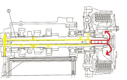
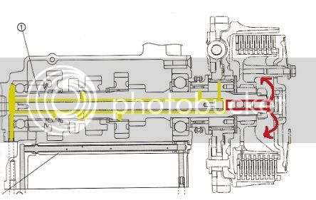
In the illustration below (provided by Mr. BR), it shows the gear shaft sprocket which supports the clutch assembly. The yellow lines represent the pressurized oil gallery, the red lines were used for discussion in a previous post. Please note that the needle bearing which the clutch basket spins on is fed by the shaft oil gallery.

FJR%20clutch-oil-path-color_zpsxq9dyrbp.jpg


That needle bearing is sealed off to the left side, but is able to flow oil out to the right side by way of that slotted flat spacer. There are 2 shallow slots machined into this hardened spacer on both sides, 4 slots total. They're not very deep, but combined provide a metered flow through this needle bearing. That is why there is an O-ring on the short shaft to the right of the ball, it seals up that oil passageway to keep it pressurized. DO NOT RE-ASSEMBLE WITHOUT THIS O-RING intact and in place !!! If it is missing, the oil pressure will be much lower, and will put critical rotating parts at risk of oil starvation.

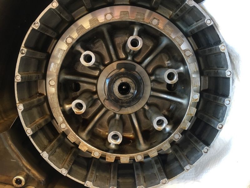
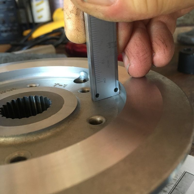
What this line drawing misses is the configuration for the back side of the clutch hub. Note that the hardened ring is inboard of the die casting edge. When the engine is running, oil from the needle bearings is metered through the 4 shallow slots and then slung outward to the back side of the clutch hub. Note the actual configuration in the picture below...

b9c7c881-8cfb-4281-a194-c11d2f2e9962_zpsnjf8zwme.jpg


This edge is angled in such a way as to catch the slinging oil from the slotted disc and channel it into the center of the clutch hub by the 2 drilled passage ways, one of which has an oil hole serving the first of the steel ring.

These Yamaha engineers are SMART
ok.gif
I like the way they design things - no wasted space, everything has a function!

I drilled my three holes, cleaned everything up and put it all back together. I made an error in procedure in that I put the flat and dished ring in first before the first friction plate, and I think that lead to a decrease in motion due to an edge being pinched, but it sorted itself out after several minutes of futzing and I was able to get the proper 2.8mm throw.

I did hit the rear brake hard and did a break in spin as directed in the manual, as the plates were probably not indexed the same way as they came out, but I kept the order and proper face out upon reassembly.

After a few blocks, the YCC-S system went into a severe chatter mode when attempting to start from a dead stop.That lead me to bleed the clutch fluid sooner in the day, but it was the Shift-66 setting which raised the engagement point RPM which rectified that situation.

Did my 3 extra holes help the shifting situation? To be honest, I really can't say for sure as the 200k miles I've put on my bikes, they never really did have any shift issues.

But, it seems to me that this bike is now shifting as good as I remember any one of my 3 bikes ever did.

This being my first go at a clutch job on one of these Yamaha Chip Controlled - Shift bikes, I had a bit of a learning experience, the service manual was quite helpful, however I want to thank several of our members here on the FJRForum who have taken the time years ago to give back to this community, and shared their knowledge. That really shortened my learning curve considerably.

Thank you 'Smart People of the FJRForum' ... this was fun - especially being 2 weeks before NAFO.
uhoh.gif


As Always ... YMMV

Brodie

rolleyes.gif


Last edited by a moderator:
The rear most friction plate is different, with a large enough I.D. to go around the outside of the flat and beveled rings, so the order that you assemble them doesn't really matter.

What I'd like to know is what the purpose of that whole rear assembly is from the wire retainer back. It's just the one friction plate sandwiched between the 1st steel plate and the back of the clutch basket, with that beveled ring as a release spring. It seems like some sort of a "secondary" clutch of some kind. Maybe it softens the engagement and increases the slip zone?
unsure.png


Last edited by a moderator:
Hey Brodie - you sure seem to like drilling holes in those baskets! Looks like what we (mainly you
smile.png
) did on my Ninja last year. The result of that work is that I don't have the plate sticking issue any more, but I think putting that small flat on the rod did end up slightly affecting the neutral-finder. The neutral finder is not quite as positive as it was prior, so reducing the pressure by opening up that flow path seems to have had an unintended consequence. As I mentioned on the Ninja forum, if I was to do it again I'd drill the holes but would pass on adding the flat.

 
Oh Yeah - Gee, I have a short memory!

That shaft is a easily replaceable item should you desire to revert back to an un-modified part. It does not pass through the gear shaft like on the FJR as the cable actuator is on the right side of the engine.

Remember, these things are supposed to be fun.

Brodie

rolleyes.gif


Nice work Brodie.

This clearly adds to our understanding of how oil is routed to the FJR clutch pack. It also illustrates the importance of the little O-ring on the outermost part of the clutch pushrod assembly.

I wish my picture above was of better resolution so we could see the cross-section of the inner clutch hub but the picture gets really grainy if I blow it up.

Thanks again for digging into this!

Best Regards,

Mr. BR

 
Nice work Brodie.This clearly adds to our understanding of how oil is routed to the FJR clutch pack. It also illustrates the importance of the little O-ring on the outermost part of the clutch pushrod assembly.

I wish my picture above was of better resolution so we could see the cross-section of the inner clutch hub but the picture gets really grainy if I blow it up.

Thanks again for digging into this!

Best Regards,

Mr. BR
Just to echo what Mr BR said...........

 
Top