FJRF003.0: Ignition Failures on FJRs

Yamaha FJR Motorcycle Forum

Help Support Yamaha FJR Motorcycle Forum:

This site may earn a commission from merchant affiliate links, including eBay, Amazon, and others.
Status
Not open for further replies.
My ignition failed prior to our fatefull ride last Sunday when our friend Sean Enlow passed away in a tragic accident. I almost didn't go for the ride because the ignition switch had a bad connection.

We had been camping at TWO and it was early morning. I figured that the moisture caused it. David, Sean's friend, loaned me some WD40, and after working it into the keyhole, the connection became constant. However, the next morning, it did it again despite the fact that I covered the ignition switch with the tent bag.

I have an '07 with about 21K miles on it. I was going to call my dealer (I purchased the YES warranty), but it hasn't done it since so I didn't. However, at home my baby stays in the garage. Washing the bike hasn't caused the problem.

 
I'm reading this with interest, now that I see several '07s afflicted.

Question: if the excess current/heat is the issue, failures would occur after an extended ride, or a combination of a not-so-long ride but very high ambient temperature, no? Just curious, as it seems to me there'd be a ton more occurences if that was the case, especially on high-mileage bikes.

With so little failures compared to number of bikes, maybe it's the tension on the wires indeed. Interesting debate. Good evening.

JC

 
Last edited by a moderator:
After following this with a great deal of interest (my 2006 was stuck at the dealership for 5 weeks this summer waiting for a switch) I am leaning more towards the heat cycling theory. A poor contact/termination design for the load and repeated "cycling" causing a cascading failure. Although there is still room for poor QC at the switch manufactureer. let's hope Yamaha can put a finer point to this when they do the recall.

Did I just see a donkey fly? Oh...not yet. I think lawyers have to be riding them...

I am also seriously thinking of adding a relay until then. On my way to CFO and just hopng that my replacement switch lasts at least the 20,000 miles the original one did until I get around to the relay idea. Won't hold my breath for a factory solution but keeping my eyes open.

Has anyone opened a Gen 1 switch and looked for the differences? Why isn't this much of an issue with them?

paul from Minnesota

 
The theory on the Gen 1 vs the Gen 2 is that the Gen 2 are running more power through the switch, since the Gen2's produce more power. Up until recently, we all thought more power was a great thing, with no strings attached. Maybe not.

 
The theory on the Gen 1 vs the Gen 2 is that the Gen 2 are running more power through the switch, since the Gen2's produce more power. Up until recently, we all thought more power was a great thing, with no strings attached. Maybe not.
All the Electrosport stator Group Buy people have not been having ignition switch problems caused by the extra power. Maybe it is just because of the low number of Electrosport installs. Or not. ;)
Yeah, I was wondering about that after I wrote that post a few minutes ago. Dunno?

 
I really wish I had taken some better pictures…

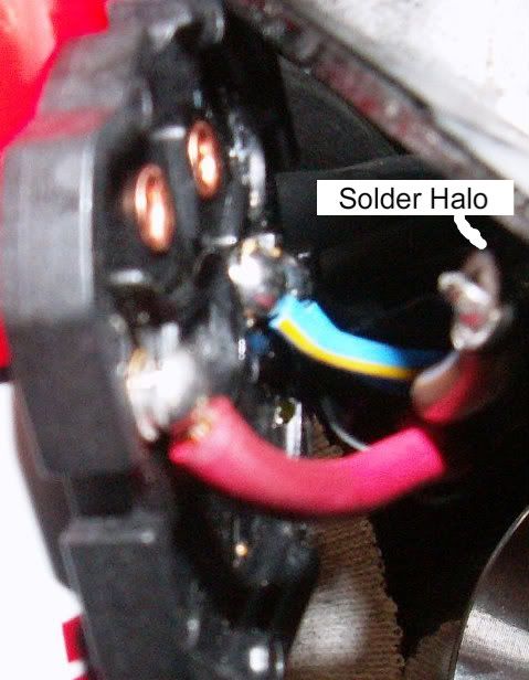
The picture below shows the Brown wire lifted from the board and connection. You can see how the solder on the Brown wire maintains the shape of the board connection. A perfectly round solder halo can be seen matching the round board connection. I would think (dangerous for me) given enough heat and stress (pull on the wire) this solder connection would not have maintained the original shape and would have flowed and taken a new shape. ??

Lifted.jpg


1911Thanks for posting the schematic.

I just want to be sure I understand.

You're splitting off of the #12 wire (red) from the battery with a #16 and running to the switch. Back out of the switch (again #16) to the relay.

The original #12 continues to the relay and meets up with the #12 brown (on different posts of course).

The relay is powered through the ign.switch and once closed, current now has another path to the bike's accessories and heat will be reduced through the switch and its contacts.

Key factor here is to have the proper size relay (rated current 50 amp +).
Sorry it took so long to reply.

Thats basically correct. On the red wire side of the ignition switch system no changes were made to the oem system, it's brown wire side that needs attention. Where the brown wire comes out of the ign sw to supply power to the loads is where to make the changes. The brown wire no longer runs back into the main harness, but is now used only to energize the pull-down side of the relay. My crude drawing is a little misleading in the battery area. Rather than split off the red #12 near the battery, I ran the wire that supplies batt power to the relay directly to the batt. Specifically, I ran the batt supply wire from a Centech APR170R relay kit to an inline fuse holder and a ring terminal and installed the ring terminal on the starter relay (batt side). I mounted the relay behind the glove box, grounded the pull-down coil to the frame, then ran the high current switched relay wire to the main harness where the brown wire from the ign sw used to plug in.

A few more facts:

Measured current draws that travel through ignition switch.

Key on/engine off (ECU, inst, taillight power)-3.76 amps

Engine running (fuel pump etc [headlight bulbs unplugged]) - add 5.29 amps

High beam headlights-add 7.54 amps

This brings us up to 16.59 amps just to ride down the road. A constant 17 amp draw traveling through 16 ga wire and small ign sw sliding contact is a LOT.

On top of the constant 17 amp minimum. Add for brake lights 2.14, turn signals 1.84 for 20.57 sitting at a light waiting to turn.

4-ways draw 3.39 amps, low beams 6.34, cooling fan and w/s motor didn't add any measurable amperage to this circuit.

 
Add me to the party roster...

1) What year FJR?;

2007

2) How many miles?;

10,800

3) Failed while running? Or while turning ignition? Or whatever?;

Failed while turning ignition on after getting gas.

4) Type of failure: Wires pulled out? Switch failure? Unknown? (pictures are useful);

Unknown at this time. However, jiggling the wires at the bottom of the harness will make the bike turn on/off/on/off/on/off.... second edit - failed solder joint and melted plastic plate

5) Actual repair performed and by what dealer;

TBD. Need to check my third party warranty, and decide what to do from there. Repair myself with relay seems the most robust approach. second edit - repaired myself

6) How many days was the bike at the dealer for service?;

NA

7) Paid for by Yamaha or not?

TBD second edit - paid myself, cost approx $40 out of pocket for relay and misc parts

8) Non-OEM accessories added that contribute to electrical draw;

Starcom, cellphone bluetooth, and iPod. edited to add: all these go thru a fuseblock directly to the battery, and not the ignition switch.

9) What did you do about the other locks (gas, side bags, seat and top case) on the bike (do you have two keys or one)?

TBD second edit - repaired original ignition switch so no issue with keys

10) Briefly, how badly were you inconvenienced by this ignition failure.

TBD. Lets see if I get home from work tonight. edited to add: Made it home, and there the feejer sits until I decide how to proceed. second edit - bike inoperable for two weeks

edited to add: Yes I filed a report with NHTSA.

 
Last edited by a moderator:
06 non AE

17,000 miles

A brief description of the problem: Its only happened twice so far, but Ive had to turn the key off and on about 10 times for the ignition to come on. After the bike was started, I reached under the ignition and jiggled the wires around to test for loose wires. No avail, the bike kept running. Im planning on replacing the switch very soon.

 
Red, your results are consistent with heat distorted internal parts that affect how the electrical contacts meet inside the switch, not a wire problem.

Replacing the switch is a good idea, but it may only buy you some time because Yamaha will be selling you the same switch as the one that is going bad right now. Hopefully Yamaha will offer an improved replacement switch soon.

 
1) Year: 2007

2) 12,400mi at the time of failure

3) Failed while turning left in a busy intersection. The bike dipped down abruptly. One could easily of low-slided the bike at that moment.

4) Type of failure: One of the large 2 wires came loose. Jiggling the wires (pushing them into the switch would allow it to run) if you let go, then it would die.

5) Dealer is covering it under warranty. Locksmith cannot re-key the switch, so they are re-keying the entire bike to the new keys.

6) It took a week for the part to arrive, then it sat at the locksmith for 4 days. I'm now taking the bike to the locksmith tomorrow for re-keying.

7) Paid for by Yamaha (re-key and part)

8) Starcom, Zumo, heated grips etc... but all connected through relays run off battery.

9) All locks will be keyed to the new ignition key.

10) Since my dealer is 45 miles from me, I'll have 4 round trips into this issue. Plus the inconvenience of it failing while 4000 miles from home.

 
Last edited by a moderator:
I finally tore into my ignition problem, and here's what I found.

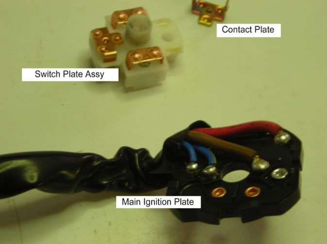
My ignition switch suffered from both problems - bad solder joint on the main ignition plate that came un-soldered, and a melted switch plate. The melted switch plate caused the contact plate in it to freeze up, and it was unable to move any longer. In this picture, you can see both failures: (note: I don't know what the official terms for these parts are so I labeled them with what I chose to call them. If anyone has heartburn over this, feel free to let me know what the correct terms are for these little critters, and I can update this post to reflect reality)

ignition_02.jpg


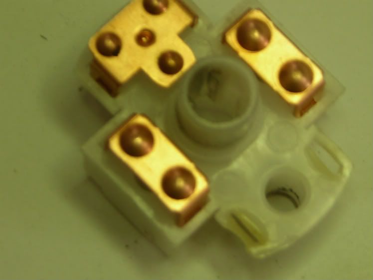
Here's a closeup of the melted switchplate (apologies for the blurry pics):

ignition_05.jpg


When I pulled the ignition switch apart, the main red wire was still attached by only one strand of the wire! This has to be the most likely cause of the melting of the plastic switch plate. The heat from all that current going through that one strand of wire had to cause the the plastic to melt.

I decided to try to repair the problem myself. Rather than buy a new ignition switch and simply install a newer version of the problem I already had, I decided to install a relay, similar to the solution that Brodie came up with look here . (BTW Brodie, if we ever meet, I owe you the adult beverage of your choice!)

Resoldering the wires to the switch plate was fairly easy and straight forward. Fixing the melted plastic switch plate took a little more work. The contact plate has tabs that need to be flattened to allow it to be removed (and you will need to push them back out before you reinstall it). Once the contact plate was removed from the switch plate, I used an exacto knife (under a magnifying light) to cut open the melted slot, back to something resembling normal, so that the contact plate could move again.

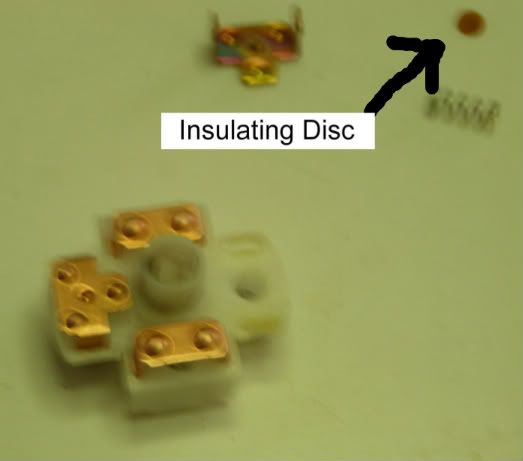
If you intend to do this same repair, the following info is very important! The contact plate sits on top of a spring, which sits on top of a detent ball. The detent ball is what gives you the "clicks" when you turn the key. Between the detent ball and the spring there is a VERY SMALL insulating disk. This disk is the only thing between the hot contact plate and ground! If you loose this disk or don't get it back in when you reassemble the switch plate, you will run the positive wire straight to ground! Sorry for the terrible photo, but this is the only picture that I got of the disk:

ignition_03-1-1.jpg


So I fixed the switch plate, and resoldered the leads to the ignition switch.

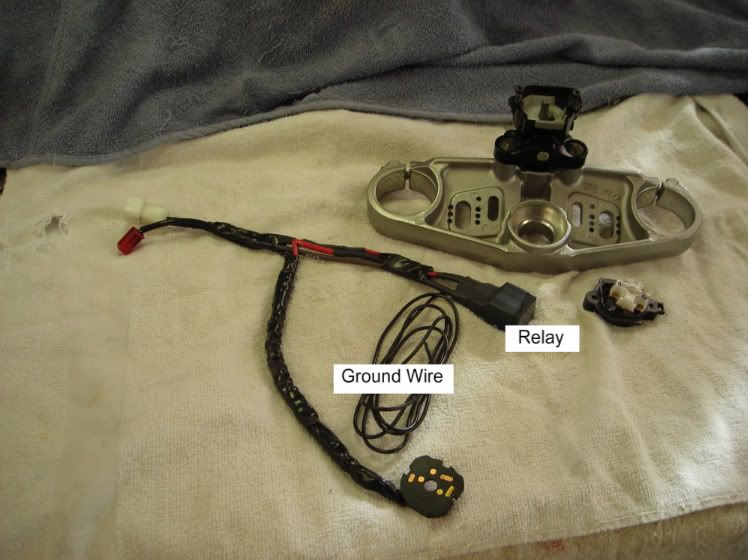
Next I spliced a relay into the system. I used almost the exact same wiring diagram that 1911 suggested look here (and 1911, if we ever meet, I owe you the adult beverage of your choice also!) Here is a picture of the relay spliced into the harness:

ignition_04.jpg


The relay ground wire is the only "new" wire in this setup. You will need to find a suitable ground location for this wire.

I installed the whole shootin' match back in and attached the relay under the front of the tank, similar to what Brodie suggested. Buttoned everything up and started the bike bike up. Success! FYI, I did do continuity checks at every step. I wanted to keep trouble shooting to a minimum.

One last observation for those who intend to replace the whole ignition switch. If you don't care about the security bolts on the bottom plate of the ignition switch, then there should be no reason to deal with two keys. If you are willing to drill out the security bolts on the bottom of your existing ignition switch, as well as your replacement switch, you can simply replace the bad switch plate and main ignition plate with the two plates from the new/good ignition. Both of these items are very easy to take out and replace once you have the bottom plate off. (note that there are two sets of security bolts in the ignition switch: on holds the entire ignition switch to the upper tripple clamp, and a smaller set of bolts attaches the bottom plate. This smaller set are the ones I'm refering to).

(edited to spell "Brodie" correctly. I wanted to give proper credit for the "Brodie Relay Fix"...no disrespect meant to the forum member who goes by Brody.)

 
Last edited by a moderator:
I finally tore into my ignition problem, and here's what I found.
My ignition switch suffered from both problems - bad solder joint on the main ignition plate that came un-soldered, and a melted switch plate...

...I decided to try to repair the problem myself. Rather than buy a new ignition switch and simply install a newer version of the problem I already had, I decided to install a relay, similar to the solution that Brody came up with look here . (BTW Brody, if we ever meet, I owe you the adult beverage of your choice!)
Neal, I may take you up on that adult beverage, I'm in Vista several times a year. We need to go ride! :)

One last observation for those who intend to replace the whole ignition switch. If you don't care about the security bolts on the bottom plate of the ignition switch, then there should be no reason to deal with two keys. If you are willing to drill out the security bolts on the bottom of your existing ignition switch, as well as your replacement switch, you can simply replace the bad switch plate and main ignition plate with the two plates from the new/good ignition. Both of these items are very easy to take out and replace once you have the bottom plate off. (note that there are two sets of security bolts in the ignition switch: on holds the entire ignition switch to the upper tripple clamp, and a smaller set of bolts attaches the bottom plate. This smaller set are the ones I'm refering to).
One thing I might add, the switch contact carrier that melted has a symmetrical design. If the floating contact plate still hangs up in use after your repair just index the plate 180 degrees to use the other pair of virgin contacts - Virtual "NEW" Switch. With the addition of the relay in the circuit it should never over heat again.

Good luck with it!

Brodie

 
Red, your results are consistent with heat distorted internal parts that affect how the electrical contacts meet inside the switch, not a wire problem.
Replacing the switch is a good idea, but it may only buy you some time because Yamaha will be selling you the same switch as the one that is going bad right now. Hopefully Yamaha will offer an improved replacement switch soon.
Thanks for the tip.

 
1) 2007

2)12384mi.

3)Failed while accelerating from a very busy stop light. A very scary few seconds getting to the side of the road.

4)broken solder joint to the Brown wire.

5)I fixed it

6) down for two days to find repair info and get a day off work.

7)85 cents for new screws

8) no electrical accessory mods

9)reused old lock

10) other than nearly getting run over to get to the side of the road, no inconvenience.

 
1) 20072)12384mi.

3)Failed while accelerating from a very busy stop light. A very scary few seconds getting to the side of the road.

4)broken solder joint to the Brown wire.

5)I fixed it

6) down for two days to find repair info and get a day off work.

7)85 cents for new screws

8) no electrical accessory mods

9)reused old lock

10) other than nearly getting run over to get to the side of the road, no inconvenience.
Don't forget to file a NHTSA report.

 
1) 2006

2) 11,500 miles approx.

3) Failed while running flat @ 35-40 mph at back of pack

4) Do not know, repaired by local dealer while I was out of town.

5) New ignition ordered and installed by Bill Eddy's Motorsports, Fayetteville, AR.

6) 5 days at dealer. .

7) I had to pay for fix.

8) New keys.

9) Day trip , after riding 200 miles some of which was the "Pig Trail" an advance rider twisting road. Lucky it happenned only 40 miles from home, bud to let me ride .itch back to my house and get trialer. on straight stretch of road, not paassing or being tailgated, in front of a place to get bike off rode and safely load on to our trailer in the dark.

 
1) 2006
2) 11,500 miles approx.

3) Failed while running flat @ 35-40 mph at back of pack

4) Do not know, repaired by local dealer while I was out of town.

5) New ignition ordered and installed by Bill Eddy's Motorsports, Fayetteville, AR.

6) 5 days at dealer. .

7) I had to pay for fix.

8) New keys.

9) Day trip , after riding 200 miles some of which was the "Pig Trail" an advance rider twisting road. Lucky it happenned only 40 miles from home, bud to let me ride .itch back to my house and get trialer. on straight stretch of road, not paassing or being tailgated, in front of a place to get bike off rode and safely load on to our trailer in the dark.
Don't forget your NHTSA report, thanks.

 
Status
Not open for further replies.
Top