FJRF009.0: Ground Spider Research

Yamaha FJR Motorcycle Forum

Help Support Yamaha FJR Motorcycle Forum:

This site may earn a commission from merchant affiliate links, including eBay, Amazon, and others.
Status
Not open for further replies.
Fan current SWAG (scientific wild ass guess), usually items are fused for twice their average running current. The radiator fans are fused @ 15 x 2 so a good guess is 7.5 amps each. On my one fan Gen I, when the radiator fan kicks on the Datel shows a major power hit.

 
Last edited by a moderator:
Manual states 6A max on fuel pump - that seems way high to me.

 
Fan current SWAG (scientific wild ass guess), usually items are fused for twice their average running current. The radiator fans are fused @ 15 x 2 so a good guess is 7.5 amps each. On my one fan Gen I, when the radiator fan kicks on the Datel shows a major power hit.
If this is a close guess, it would be the highest power consumer and begs the question...

[SIZE=14pt]For the guys that have actually had spider failures, does your riding condition make the fans run a lot? (e.g. Do you sit in traffic often or for long periods of time?)[/SIZE]
Well, as a data point, my S4 (aka Black Widow) spider failed during the Jan 3 cold snap in Flori-duh, the temp was in the low 60s. I was running the heated jacket, but that's separately wired from the Batt. The failure happened during riding, so the fans were NOT on at the time.

 
Well, as a data point, my S4 (aka Black Widow) spider failed during the Jan 3 cold snap in Flori-duh...The failure happened during riding, so the fans were NOT on at the time.
Hmmm, ya, well... Sorry to hear that the Black Widow bit ya. Sorry about the cold snap too, I'm pleased that it has gotten up to 13°F and the wind has dropped to 20 mph today ;) :lol:

The spiders die from a long war of attrition, I'm sure your FLA summers have had your fans on a lot. I was very serious when I earlier suggested using a hex brass rod as a terminal to attach the spider wires to. In industry I've used copper blocks as grounding strips because of the heat transfer capabilities as well as the electrical conductivity. The brass won't do quite as well, but it will still do a pretty good job of conducting both heat and current. This is really what we are trying to do, keep the connections flowing 100% of the current which will in turn avoid heat in the first place. The brass will then work as a heat sink and readily dissipate heat and not create hot spots.

 
Last edited by a moderator:
Fan current SWAG (scientific wild ass guess), usually items are fused for twice their average running current. The radiator fans are fused @ 15 x 2 so a good guess is 7.5 amps each. On my one fan Gen I, when the radiator fan kicks on the Datel shows a major power hit.
If this is a close guess, it would be the highest power consumer and begs the question...

[SIZE=14pt]For the guys that have actually had spider failures, does your riding condition make the fans run a lot? (e.g. Do you sit in traffic often or for long periods of time?)[/SIZE]
These are both very good points. If the fans grnd threw the Black Widow spider (and I don't doudt the findings RZ350 must have spent hours doing) then this may be a big part of the problem.

As Allan said earlier, my volt gage also drops pretty good when the fans come on.

So if it's the fans then we should be seeing more failures in the warmer climates as well as riding conditions. I know my fans almost never run here in the Adirondacks, but there is only 2 seasons, :cold: winter & July 4th. Maybe that is why my spiders all looked OK.

 
Yamaha is serious about powering the radiator fans. Each fan gets power which comes through an individual 15 amp fuse, a common radiator fan relay (one relay for both fans), the relay power bypasses the ignition switch, goes through the main power fuse and straight to the battery. The only reason the radiator fans switch is because the ECU controls the radiator fan relay. Grounding the fans, not so serious, the schematic shows the fan grounds nebulously going to a common ground buss.

 
Last edited by a moderator:
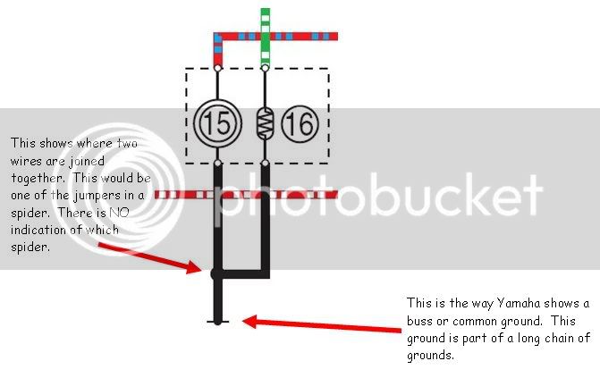
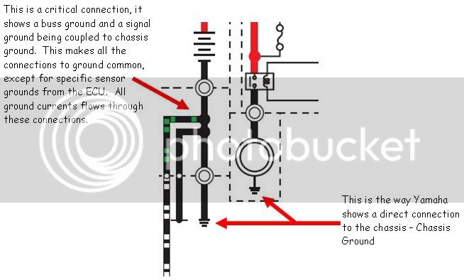
Each field that uses electricity and electronics can show wiring schematic symbols a bit differently. This is my take on how Yamaha's schematic symbols work:

BussGround2.jpg


ChassisGround2.jpg


This is one type of grounding block. I've written to Dave suggesting a smaller, more simple grounding block. This would be the ultimate way to deal with the grounds.

02207.jpg


Last edited by a moderator:
Well, as a data point, my S4 (aka Black Widow) spider failed during the Jan 3 cold snap in Flori-duh...The failure happened during riding, so the fans were NOT on at the time.
Hmmm, ya, well... Sorry to hear that the Black Widow bit ya. Sorry about the cold snap too, I'm pleased that it has gotten up to 13°F and the wind has dropped to 20 mph today ;) :lol:

The spiders die from a long war of attrition, I'm sure your FLA summers have had your fans on a lot. I was very serious when I earlier suggested using a hex brass rod as a terminal to attach the spider wires to. In industry I've used copper blocks as grounding strips because of the heat transfer capabilities as well as the electrical conductivity. The brass won't do quite as well, but it will still do a pretty good job of conducting both heat and current. This is really what we are trying to do, keep the connections flowing 100% of the current which will in turn avoid heat in the first place. The brass will then work as a heat sink and readily dissipate heat and not create hot spots.
Well I haven't gone through all 200+ comments but I guess I should check this out some time. My fans don't come on that often either. I do ocasionaly smell rubber burning and haven't quite figured that one out yet. I am thinken my YES plan is gonna kick in someday. As soon as I get some free time I will look under the hood and get into this project.

Dave

 
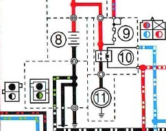
When I look at the diagram I have access to (for a USA '06 AE), it shows a ground connector where you indicate "a critical connection", far left of my picture (it may be on your diagram but cut off):

groundconnectorquery.jpg


Looks unlike a spider connector. As you suggest, it seems to be where all the other grounds come back to the wire between battery negative and chassis (which would certainly make it critical!).

Do we know what type of connector this is, whether it's ever given a problem, and where it is? Seems to me it would be well worth checking out.

 
Last edited by a moderator:
Each field that uses electricity and electronics can show wiring schematic symbols a bit differently. This is my take on how Yamaha's schematic symbols work:
BussGround2.jpg


ChassisGround2.jpg


This is one type of grounding block. I've written to Dave suggesting a smaller, more simple grounding block. This would be the ultimate way to deal with the grounds.

02207.jpg

I was just about to head out to the garage and ground the spider to my fuseblock. Would this approach accomplish what you suggest here? Thanks

 
my S4 (aka Black Widow) spider failed during the Jan 3 cold snap in Flori-duh, the temp was in the low 60s. I was running the heated jacket
OMFG!!! SOMEONE needs to read THIS thread!
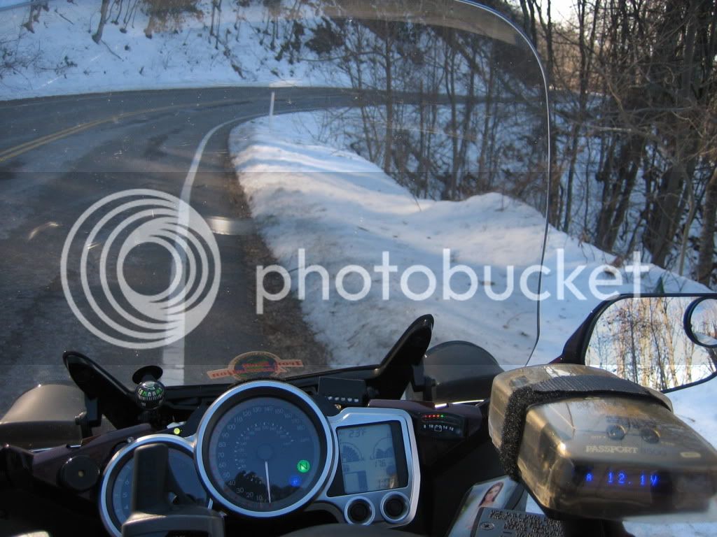
Damn I picked a wrong day to make a typo, I mean to say 40s F. Btw, I'll take 20s F on real roads over 90s in Flori-duh any day! As long the roads aren't all iced up I'm Lovin' it. Here is my New Years 2009 trip to GA, TN...23F was the highest temp...

New Years 2009 in the Mountains

IMG_6091.jpg


Looking at the FSM wiring diagram, and looking at the wiring on the bike. It looks to me like the black wires (in the diagram) that end with one line threw the end is a spider, and where 2 wires meet to look like a splice may also be a spider.

Also I only see 3 chassis grounds.

-neg battery cable

-starter

-ABS ECU

So everything else is going threw a spider. And we know the BLACK WIDOW is the one that all other B spiders go threw. So all lights, fans, shield drive etc. are going threw it.

This is worse than I thought, because of the fans. I didn't think to check them until it was mentioned. I just assumed (I know) they would go to chassis with something like that. While we're on the subject, how many amps do the headlights and shield drive draw ?

Here's an idea. ;) Maybe good , maybe not so good. Check it out and let me know.

So maybe if someone didn't want to mess with the spiders they could remove the original grnd wires from the fans, ground the fans to the chassis by making up 2 new wires, then hook the original 2 fan grnd wires (previously removed) to the chassis. This will take the fans out of the equation and add 2 chassis grnd wires to the S4 (BLACK WIDOW) spider without modifying it.

Then they could tap into the Acc. jack or the glove box grnd wire or both, then run them to chassis also. This will add 1or 2 grnd wires to the S6 spider, and should take care of the headlights and shield drive.

I think that would take care of the overload situation. Of coarse they would still have to clean, and grease all the spiders once a year.

I couldn't have come up with this idea if not for RZ350s excellent chart of what goes where. Thanks RZ

More food for thought; A.C.

 
Looking at the FSM wiring diagram, and looking at the wiring on the bike. It looks to me like the black wires (in the diagram) that end with one line threw the end is a spider, and where 2 wires meet to look like a splice may also be a spider.
Also I only see 3 chassis grounds.

-neg battery cable

-starter

-ABS ECU

....So maybe if someone didn't want to mess with the spiders they could remove the original grnd wires from the fans, ground the fans to the chassis by making up 2 new wires, then hook the original 2 fan grnd wires (previously removed) to the chassis. This will take the fans out of the equation and add 2 chassis grnd wires to the S4 (BLACK WIDOW) spider without modifying it...
I was incomplete in the text that accompanied the schematic screen shots. I should have been clear that the ground buss/common grounds ARE indeed the spider wires.

It may be a bit before Dave gets back to me about perhaps making simple grounding blocks to replace the spiders. The blocks will be easier than running new wires (I think) and will solve the electrical and heat problems of the OEM Black Widows.

Edited to add:

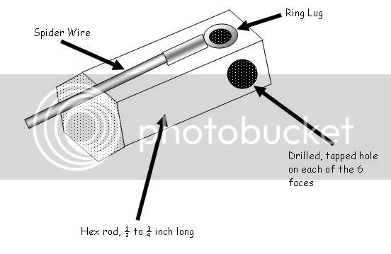
Alan draws with a blunt crayon -- Brass hex rod stock, 6 wires per spider, six faces on the rod stock. See the link in the paragraph above where I describe the block in more detail.

GroundBlock.jpg


Last edited by a moderator:
I think Grumpy has the right idea, replace the spider with a non corrosive one. I know almost nothing about electronics other than a HS class. Are they that uncommon that someone does not make replacements that would work?
Not always a good idea. Certain dissimilar metals corrode very quickly due to galvanic corrosion. You do not want this.

As along as there are no issues with your current connections, pull out the spider, clean it up. Use CRC electrical contact

cleaner on the harness contacts. Install then remove the spider. Let contact cleaner dry out and liberally apply dielectric grease

into the connector contacts, then insert the spider.

 
Last edited by a moderator:
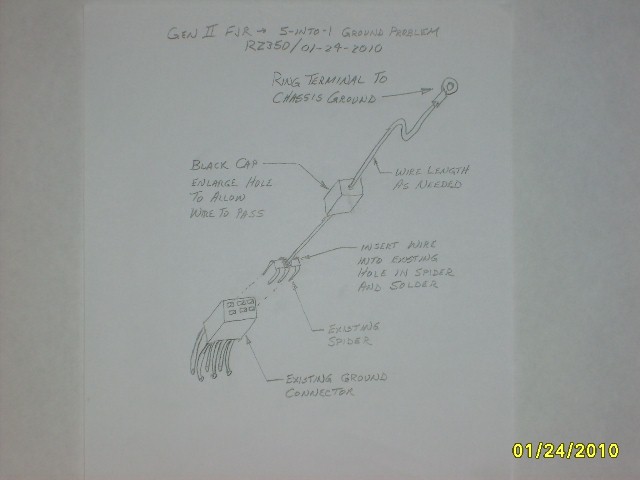
I had a chance to ponder on this grounding issue over the weekend. I subscribe to what I will call the [SIZE=12pt]"5-into-1"[/SIZE] overload theory that some of the others do. I believe only one of the six pins is causing the overheating problem, otherwise you might be seeing issues at the other end of the harness where it connects to the actual component. Where I work, we design our vehicle harnesses using this same grounding method (ground connectors scattered throughout the harness) but with a different type of connector. It is critical that the one pin leading back to ground be sized to carry the total current (plus some safety factor). We’ve even found that “chassis” grounds scattered around prove to be unreliable at times as well, but that’s another story. My guess is Yamaha is overloading some of these. (Wasn’t the ignition switch recall related to an overload issue too?) My harness study should give us some insight here.
I’m going to offer an alternate solution to you DIY’ers for giving the ground connector a second path to help lighten the load on that one undersized spade terminal in the ground connector. It simply requires some wire and ring terminals. It doesn’t require any modification to harness itself, but only to some of the components inserted in it. You can also do the soldering away from the bike if you choose. Hopefully you can see and understand my sketch.

4302480458_d1a161b05b_o.jpg


I’m hoping Yamaha steps up to the plate and solves this one for us. I’m reluctant to go to drastic measures as some have done to ultimately solve this problem. I fear Yamaha will say I took matters into my own hands and damaged my harness beyond an acceptable limit for OEM repair and the claim will not be covered. If I had to venture a guess, I would say Yamaha’s fix will avoid modifying or replacing the existing harness (too costly) and head towards a “snap-in” solution such as Brodie’s. I know that’s what I would be forced to do at work if this problem arose.

Okay - go ahead and pick it apart…


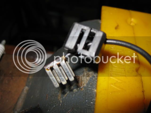
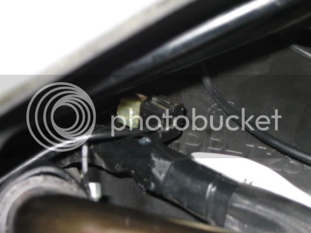
I used your method, but put the wire through the side of the cap and ran the ground to the fuse block. The cap snaps back on securely and I zip tied it just to make sure.

groundspider008.jpg


groundspider013.jpg


Status
Not open for further replies.
Top