ionbeam
2 FUN
The ECU is a computer, a totally digital animal, it lives and breathes O's and 1's only. The ECU takes in analog signals which can vary from 0 to 14 volts, then runs the voltages through an Analog to Digital Converter (ADC) to make them digestible by the computer. Because of the way the ADC works it likes voltages to be very, very clean, highly regulated 5 VDC and very, very clean, highly regulated 9VDC or 12 VDC. Sensors like the TPS gets 5VDC.
The normal electrical system in all automotive applications is 'dirty', full of little voltage ripples on both ground and power. The ECU contains a DC to DC converter (DC/DC) which separates the main electrical system's power and ground then outputs highly regulated 5VDC/12VDC plus isolated grounds to the various sensors. If you go to someplace like the TPS to make a voltage reading you must use the ground wire going to the TPS for the Digital Multi-Meter's ground because the ground originates from the ECU's DC/DC converter and is isolated from the chassis and battery ground. In fact, if you put one DMM lead on the TPS ground and the other DMM lead on the chassis or battery ground you would likely read a randomly fluctuating voltage which could be several volts.
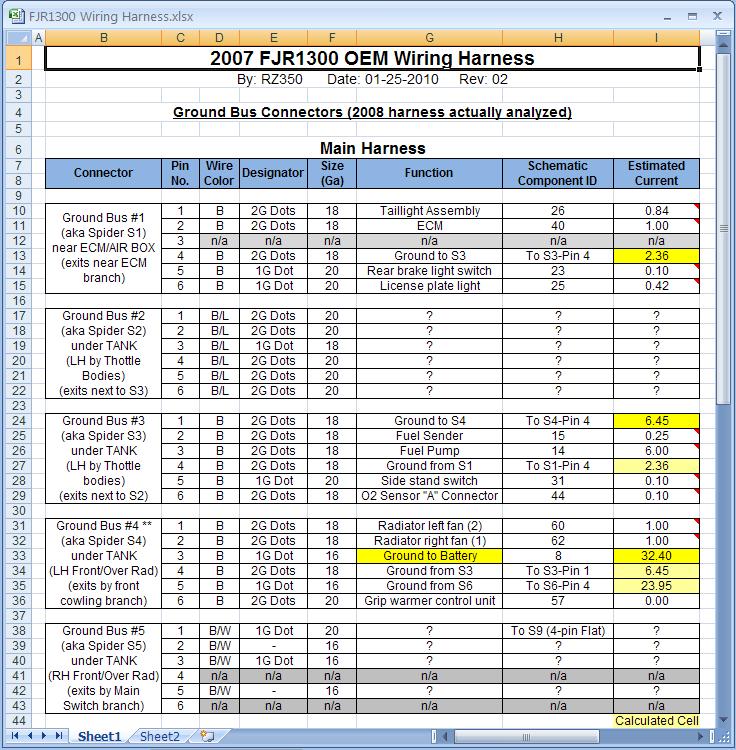
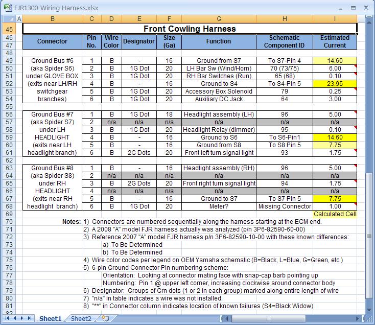
The grounds associated with the ECU should not tied to chassis ground or battery ground. It looked to me like the '06 schematic showed that wires with dots were related to the ECU and the solid black wires were battery/chassis ground.
As Art notes, the sensor inputs to any computer are not very robust and should be treated with care. In fact, some needle type multi-meters can damage computers, it is always best to use a DMM when troubleshooting ECU related wires.
:lazy:
The normal electrical system in all automotive applications is 'dirty', full of little voltage ripples on both ground and power. The ECU contains a DC to DC converter (DC/DC) which separates the main electrical system's power and ground then outputs highly regulated 5VDC/12VDC plus isolated grounds to the various sensors. If you go to someplace like the TPS to make a voltage reading you must use the ground wire going to the TPS for the Digital Multi-Meter's ground because the ground originates from the ECU's DC/DC converter and is isolated from the chassis and battery ground. In fact, if you put one DMM lead on the TPS ground and the other DMM lead on the chassis or battery ground you would likely read a randomly fluctuating voltage which could be several volts.
The grounds associated with the ECU should not tied to chassis ground or battery ground. It looked to me like the '06 schematic showed that wires with dots were related to the ECU and the solid black wires were battery/chassis ground.
As Art notes, the sensor inputs to any computer are not very robust and should be treated with care. In fact, some needle type multi-meters can damage computers, it is always best to use a DMM when troubleshooting ECU related wires.
:lazy:
Last edited by a moderator:
")