FJRF009.0: Ground Spider Research

Yamaha FJR Motorcycle Forum

Help Support Yamaha FJR Motorcycle Forum:

This site may earn a commission from merchant affiliate links, including eBay, Amazon, and others.
Status
Not open for further replies.
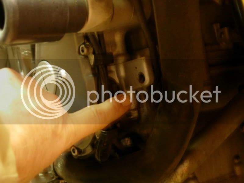
I can't get any good pics of the spider near the left fork, maybe Smitty141 has some since this was the spider he had to repair. This is from his writeup
Maybe this will help, in relation to the coolant reservoir at the bottom right.

DSCN0932.jpg


Gentlemen

I am in the process of tooling up for another *harness project.

Currently my '06 AE is symptom free, and as of last november all the "grounding" connectors look to be in good shape. I injected Silicon Dielectric grease way back when the bike was 2 months old. However, since JamesK also greased his connectors, albeit a little later than I did mine, and still fell prey to the thermal runaway, I wish to take a pre-emptive course with my bike.

I have located the female half of the connector (Jim Davis at Eastern Beaver) and will be getting 40 of them in a week or two, and along with them their associated male pins. That should net me up to 4 prototype Harnesses. I have also invested in the PressMaster crimping tool ($$$) sized for the .090 series pins.

My plan is to make a grounding harness which will reach all 8 of these connectors. The other end will terminate at the battery negative terminal. The 6 male pins will each have an 18 gage wire crimped to them. These wires will immediately be butt spliced into a 14 gage pigtail wire, which when joined with other pigtails will be butt spliced to a 10 gage main line back to the battery. This will add to the ground wire within the OEM harness - not take the place of it. The goal is to make a single harness that will be plug and play.

I have a question for the Electrical Engineer Types of the forum. Several members have gone this route of having gathered and soldered the leads and running a secondary pigtail wire to chassis ground.

Is this going to cause more harm than good?


Will this pigtail cause problems by having a different potential than the ground path within the OEM harness?


[SIZE=12pt][/SIZE]

Will it set up a harmful

Ground Loop
situation?


I realize the absolute best fix will be to cut the terminal off completely, strip and crimp a splice cap in place, then add solder to form a good electrical bond. Encapsulate with heat shrink, and secure the repair alongside the main harness out of harms way. Lets face it - not that many owners will (or can) go through the extra effort to do a professional job like that. A harness, on the other hand, will be the most palatable and easiest method of addressing the greatest number of bikes out there.

Your thoughts please!

Brodie

[SIZE=8pt]*[shamless plug] By the way, I still have about 10 of my Ignition Relay Harnesses for sale if anyone is interested. :rolleyes: [/shamless plug][/SIZE]

 
Last edited by a moderator:
To answer your "ground loop" question: Actually, the way the factory designed the shared ground already sets up the conditions necessary for a ground loop to occur by having multiple circuits sharing a ground wire from the spiders back to common ground. In fact, one of the standard failure modes of (at least one of) the spiders failing demonstrates a ground loop situation when return current from one device is back biasing another one (indicator lights all on) because the intended ground wire path is interrupted and the lights present an alternate path to ground.

Typically, ground loops are only a problem for devices that are sensitive to ground (aka common) noise like audio and in some AC applications, especially RF. Since the circuits we are talking about are DC applications, and I do not think any of them are noise sensitive, I would say your design plan is safe. As I mentioned before, it would be best to understand what all of the circuits are that are being grounded in each of the spiders.

As an aside, I would say that since you just providing an alternate path to ground for each individual line in the spider, it is only necessary to bring that ground to the same common point that the original ground wire in the harness went. That is (most likely) just the frame. I seriously doubt the spider's grounded conductor goes all the way back to battery terminal. I know lots of people advocate running ground wires all the way to the battery for simplicity sake, but it really is overkill.

[edit] One other point about ground loops: There really is technically no "ground" on a motorcycle as the common (negative) side of the electrical system is never brought to earth ground potential. But for all intents the motorcycle's frame can be considered the equivalent of ground. Ground loops happen because earth grounds are not always at the exact same potential, and so unintentional current may flow through the ground conductors between the (multiple) ground points. The likelihood of two points of a motorcycles frame "ground" being at a different potentials from each other is much lower than two true earth grounds.

 
Last edited by a moderator:
Gentlemen
I am in the process of tooling up for another *harness project.

[SIZE=8pt]*[shamless plug] By the way, I still have about 10 of my Ignition Relay Harnesses for sale if anyone is interested. :rolleyes: [/shamless plug][/SIZE]
Kudos Brodie for doing this mod and offering it up. I already soldered mine and added an additional wire to ground for each but like you say that isn't for everyone. I have just 2 thoughts on your proposed mod.

Pros

Anyone will be able to accomplish it relatively easy.

It will be very cost effective compared to a failure on the road, or a harness out of warranty.

I think it will solve the problem.

Cons

The only thing I don't like initialy is you are still using the same type of pins and sockets, which are inadequate in my opinion.

However, it seems that the burnt pins have been found on the larger wire(s) of the splices, which probably are the ones carrying the multiple currents to ground. Your harness will take the load off of those original ground wires (or at least share the load) which I believe will solve the problem.

So my con is not really a con at all. I think this is a great idea that I would do if I hadn't already soldered my harness.

This harness issue is definitely one of Yamahas darker hours.

 
It's Brodie to the rescue, again. Great idea Brodie, and I think it will solve this problem once and for all. Both Fred & Bob make good points, but I don't think these will prevent your harness from doing it's intended job. I agree with Fred that there is no reason to run the common ground wire from your harness back to Batt -ve, since as you can see from the picture posted by rbentnail the Batt -ve is terminated directly on the Engine case.

DSCN0922.jpg


Since I did my fix using Bob's method (grounding each soldered up spider to a nearby chassis bolt) I did confirm that all the points I was grounding to were at the same potential, and they seem to all be the same, at least to within the sensitivity of my DMM.

Brodie, Yamaha should put you on their payroll.

 
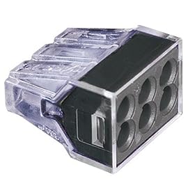
Just curious to see if you think these two options might do the trick?

Idea #1:

I was thinking of ordering these, filling them with die electric grease.

41KZ6GmSW4L._SL500_AA280_.jpg


Found here, 10 pack is $6,99!

Idea #2 (overkill idea, I think):

I was thinking of ordering these, filling them with die electric grease. Running 1 or 2 additional grounds wires.

41cGffcHATL._SL500_AA280_.jpg


Found here, 50 pack is $12,99!

But before I ordered I thought of seeing what your thoughts would be.

 
Just curious to see if you think these two options might do the trick?
Idea #1:

I was thinking of ordering these, filling them with die electric grease.

Found here, 10 pack is $6,99!

Idea #2 (overkill idea, I think):

I was thinking of ordering these, filling them with die electric grease. Running 1 or 2 additional grounds wires.

Found here, 50 pack is $12,99!

But before I ordered I thought of seeing what your thoughts would be.
With additional failures taking place it's is becoming more evident that the "final" solution is to provide an alternate ground path, not just fix the connection. I am sure these would help, but I don't think they would provide the complete solution.

 
To those who advocate soldering crimped connections, this may give you some food for thought.

https://www.ch601.org/resources/crimpsolder.htm

I admit to having soldered many a crimped connection based on the belt and suspenders principle, but I am slowing coming around to this guy's way of thinking.

I fail to see any good reason to connectorize the ground junctions. The only reason to use a connector in the first place is to make it easy to break a connection for component replacement, or where it is necessary to disconnect components for easier disassembly. Neither seems to apply in this case. Surely it would have been cheaper and quicker (not to mention far more reliable) for Yamaha to assemble the wiring harnesses by crimping together the return (not "ground") connections to a single lead which is tied to the frame. When I do get around to inspecting my "spider" connections, this is exactly what I plan to do: cut off the wires at the connector, and crimp them together with a high quality crimping sleeve, which will be covered by the glue-filled style of heat shrink tubing. No soldering is necessary. The glue-filled style of heat shrink tubing is completely water proof in my experience. I might replace the lead that makes connection to the frame with a larger gauge wire, based on some of the comments I have seen here.

 
I still believe that a soldering a joint (whether it's crimped or the wires are properly twisted together) offers the ultimate long-lasting connection I think your proposed method would also work.

I think you might have difficulties getting the crimping tool big enough to crimp together a bundle of wires to the two spider grounds at the front under the tank. There really is almost no room under there...

 
With additional failures taking place it's is becoming more evident that the "final" solution is to provide an alternate ground path, not just fix the connection. I am sure these would help, but I don't think they would provide the complete solution.
I thought option 2 would solve that, as you could have 2 additional ground wires.
My bad, I didn't notice the extra holes :blink: Yes, guess these would work.

 
I ordered (5), 8 wire connector for $3,99. I will test a few things out and see how it goes. Soldering is always a good option just looking for something quick and easy.

$3,99 e-bay option

41cGffcHATL._SL500_AA280_.jpg


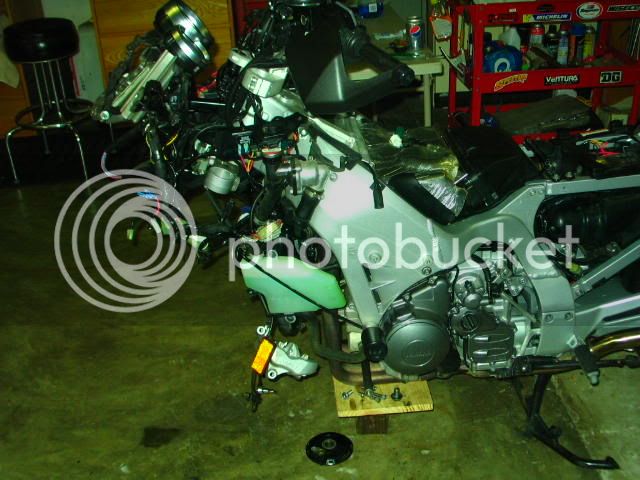
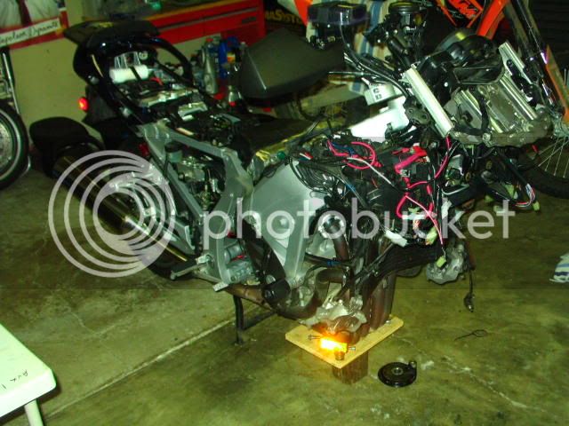
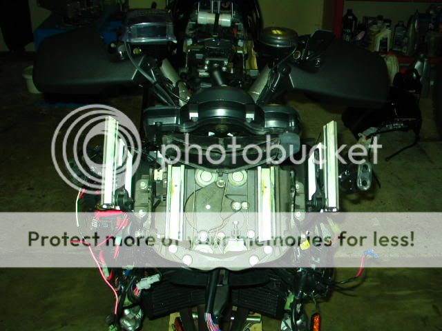
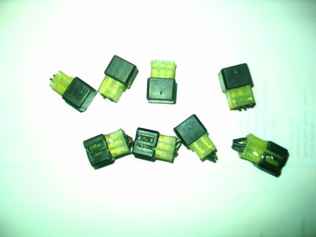
Well as much as I hated to remove the front of my bike.. I killed all the spiders today, with a cut, strip, twist, and solder.... 8 total are now removed.. I did see a hint the connector under the left side fuel tank starting to discolor. That tells me it was on the way to trouble. It just made sense to remove these at home, and not chance a problem on the road.

If anyone wants these's they are free, just pay shipping!!!

Smitty

002-8.jpg


Down side your bike looks like this...Forks on the bench for service...

006-8.jpg


005-10.jpg
004-9.jpg


Last edited by a moderator:
Well as much as I hated to remove the front of my bike.. I killed all the spiders today, with a cut, strip, twist, and solder.... 8 total are now removed.. I did see a hint the connector under the left side fuel tank starting to discolor. That tells me it was on the way to trouble. It just made sense to remove these at home, and not chance a problem on the road.

Damn that looks all too famiiar. <_<

 
Just curious to see if you think these two options might do the trick?
Idea #1:

I was thinking of ordering these, filling them with die electric grease.

41KZ6GmSW4L._SL500_AA280_.jpg


Found here, 10 pack is $6,99!

Idea #2 (overkill idea, I think):

I was thinking of ordering these, filling them with die electric grease. Running 1 or 2 additional grounds wires.

41cGffcHATL._SL500_AA280_.jpg


Found here, 50 pack is $12,99!

But before I ordered I thought of seeing what your thoughts would be.
IMHO you're just replacing one crappy connector with another. If I read correctly, these are nothing more than a push-type connector similar to the el-cheapo connections found on the backs of household receptacles and light switches. Don't waste your time or money with this crap, trying to cut corners and save money. In the long run you're gonna be in the same boat. Just solder the damn things and be done with it.

 
IMHO you're just replacing one crappy connector with another. If I read correctly, these are nothing more than a push-type connector similar to the el-cheapo connections found on the backs of household receptacles and light switches.<snip>
Jc

I tend to agree, if you research these connectors they achieve the electrical connection with a spring clip. The surface to surface contact is even less than the spyder/connector assembly it would replace. I'm afraid that if you did manage to install them in the restricted space on your bike you would be severely disappointed.

FWIW, here is a PDF for the Wago catalog which lists the connectors you refrenced...https://www.wago.us/downloads/51216511.pdf

Brodie

 
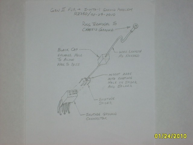
I had a chance to ponder on this grounding issue over the weekend. I subscribe to what I will call the [SIZE=12pt]"5-into-1"[/SIZE] overload theory that some of the others do. I believe only one of the six pins is causing the overheating problem, otherwise you might be seeing issues at the other end of the harness where it connects to the actual component. Where I work, we design our vehicle harnesses using this same grounding method (ground connectors scattered throughout the harness) but with a different type of connector. It is critical that the one pin leading back to ground be sized to carry the total current (plus some safety factor). We’ve even found that “chassis” grounds scattered around prove to be unreliable at times as well, but that’s another story. My guess is Yamaha is overloading some of these. (Wasn’t the ignition switch recall related to an overload issue too?) My harness study should give us some insight here.

I’m going to offer an alternate solution to you DIY’ers for giving the ground connector a second path to help lighten the load on that one undersized spade terminal in the ground connector. It simply requires some wire and ring terminals. It doesn’t require any modification to harness itself, but only to some of the components inserted in it. You can also do the soldering away from the bike if you choose. Hopefully you can see and understand my sketch.

4302480458_d1a161b05b_o.jpg


I’m hoping Yamaha steps up to the plate and solves this one for us. I’m reluctant to go to drastic measures as some have done to ultimately solve this problem. I fear Yamaha will say I took matters into my own hands and damaged my harness beyond an acceptable limit for OEM repair and the claim will not be covered. If I had to venture a guess, I would say Yamaha’s fix will avoid modifying or replacing the existing harness (too costly) and head towards a “snap-in” solution such as Brodie’s. I know that’s what I would be forced to do at work if this problem arose.

Okay - go ahead and pick it apart…

 
Last edited by a moderator:
My bike looks just like Smittys, :blink: because I killed the 8 spiders today. Before doing so I checked them & did some diag.

They were all fine ,and working as designed. So next I got out the ohm meeter and did some checking to see how Yammie has them wired (in series or parallel to ground). What I found is shocking, and no wonder they are failing. They are wired in series, so if one fails it will keep others from getting ground.

It looks like there is 2 spiders that each have one wire going to ground. These 2 spiders that are doing all the work are under the tank, front left and front right. The front left (the one that is failing the most) has 6 wires going to it, 1 goes to ground, and the other 5 wires go to 5 other spiders. So when this one fails it takes out 5 others with it. :glare: No wonder this one is failing.

The right front spider supplies ground to 1 other so not as much demand on this one.

If you unplug the left front, under tank spider you loose ground to, all 3 in the fairing, the 1 by the ECM, and 1 of the 2 by the left throttle body.

Unplug the right front and you loose ground to the 1 remaining spider at the TB.

Also there is a white 6 pin plug at the left front fairing (under the glove box) that connects the 3 fairing spiders to the rest. So make sure it is clean and greased or you could loose the front 3 spiders. Can't solder this or you won't be able to get the top fairing off.

I did like Smitty did, cut off connectors, and soldered the wires together with an additional wire going to the frame. Since all was working fine I didn't see the need to run 8 additional grnd wires. I added 3 grnd wires. One has the 3 dash spiders on it, the other 2 added grnd wires have 3 spiders on one, and 2 on the other.

I didn't read all 7 pages on this topic, so if someone already posted this info, sorry.

Ride Safe; A.C.

 
RZ

That is a good idea, but what if the connection gets dirty between the spider and connector ? I think the same failure may accure.

Mine were fine with 27000 miles so I don't think it's as much overload as a dirty connection issue. But it could be a little of each. Like I said in earlier post there is 1 connector that is doing most of the work, and it is up front, over top of the radiator so it may be getting wet, and corroding. Once it gets a little corrosion, then resistance, then heat, and the other 5 spiders are trying to go threw it, now it may be overloaded.

So I eliminated the bad connection by soldering, and added some more ground paths. I hope that takes care of it.

edit; After thinking about it, you may be right. Maybe the heat from being overloaded is starting or helping the corrosion. It is the spider that is acting as a junction box for 5 others that is failing mostly. So actually overloading makes sence. And your 5 into 1 idea looks nice and easy, and it does look like something Yammie would use to fix this.

Who knows, it's like the chicken or the egg.

 
Last edited by a moderator:
Fascinating reading folks. Great job!

Even and electrical ******* like me appreciates the collective attempt to re-engineer what Yammie has ****** up.

Oh, and did I mention how glad I am to have a Gen I?

 
Status
Not open for further replies.
Top