FJRF009.0: Ground Spider Research

Yamaha FJR Motorcycle Forum

Help Support Yamaha FJR Motorcycle Forum:

This site may earn a commission from merchant affiliate links, including eBay, Amazon, and others.
Status
Not open for further replies.
My bike looks just like Smittys, :blink: because I killed the 8 spiders today. Before doing so I checked them & did some diag.
They were all fine ,and working as designed. So next I got out the ohm meeter and did some checking to see how Yammie has them wired (in series or parallel to ground). What I found is shocking, and no wonder they are failing. They are wired in series, so if one fails it will keep others from getting ground.

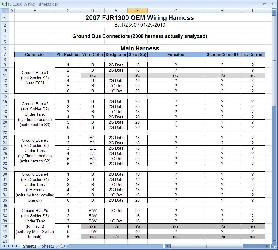
It looks like there is 2 spiders that each have one wire going to ground. These 2 spiders that are doing all the work are under the tank, front left and front right. The front left (the one that is failing the most) has 6 wires going to it, 1 goes to ground, and the other 5 wires go to 5 other spiders. So when this one fails it takes out 5 others with it. :glare: No wonder this one is failing.

The right front spider supplies ground to 1 other so not as much demand on this one.

If you unplug the left front, under tank spider you loose ground to, all 3 in the fairing, the 1 by the ECM, and 1 of the 2 by the left throttle body.

Unplug the right front and you loose ground to the 1 remaining spider at the TB.

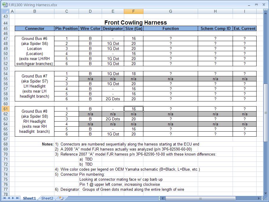
Also there is a white 6 pin plug at the left front fairing (under the glove box) that connects the 3 fairing spiders to the rest. So make sure it is clean and greased or you could loose the front 3 spiders. Can't solder this or you won't be able to get the top fairing off.

I did like Smitty did, cut off connectors, and soldered the wires together with an additional wire going to the frame. Since all was working fine I didn't see the need to run 8 additional grnd wires. I added 3 grnd wires. One has the 3 dash spiders on it, the other 2 added grnd wires have 3 spiders on one, and 2 on the other.

I didn't read all 7 pages on this topic, so if someone already posted this info, sorry.

Ride Safe; A.C.
Good job roadrunner. could you be specific as to which spiders by the TB on the left side of engine that each (LH or RH ) spider control? I am thinking of doing the 5 into 1 on the spider that is under the left lower fairing panel, the EC spider and the one by the TB that the same left hand spider controls. That would take the load of three of the downstream spiders off of that LH spider's circuit, leaving only the ones in the front of the fairing. This would be real close to the load that the RH spider is controlling. Does this sound resonable. I really don't want to pull the whole fairing off. Just in case though I have a list of all Yamaha dealers from St.Louis to Daytona (bikeweek),via MO.,TN., MS., AL.,FL just in case. Please chime in abbout this . And thanks to everybody that has worked on this problem. Go Fast ,Turn Left
dirttracker30

Thanks for the ada boy.

I think I know what your saying. The culprit spider is under tank, left front. When it is unhooked 5 others loose there connect to ground. All 6 of these have the same color wire. The wire color is black with green dot. So the spider you are looking for is the one with that color wire.

The other spider, right,front under tank. Wire color is black with white tracer. This one, when removed takes ground away from the other spider at TB, and it's color is black with a blue tracer.

Hope this helps;

A.C.

 
RZ 350

That wiring chart looks awesome. That is what I was going to do, but decided it would take me to long. So I decided to see if they were in parallel or in series and that is when I found what I did. I didn't even check to see what wire goes were, all I did is unplug spiders and checked others to see what happened. All I really know is when the one under tank, left,front (Black Widow) :dribble: is unplugged 5 others follow and when the right,front, under tank is unplugged 1 other follows. So your chart, knowing what goes were could be helpful.

Thanks for the effort; A.C.

 
/Snip/
The culprit spider is under tank, left front. When it is unhooked 5 others loose there connect to ground. All 6 of these have the same color wire. The wire color is black with green dot. So the spider you are looking for is the one with that color wire.

The other spider, right,front under tank. Wire color is black with white tracer. This one, when removed takes ground away from the other spider at TB, and it's color is black with a blue tracer.

Hope this helps;

A.C.
Road Runner:

Along with previous pictures posted, this is great info to identify/verify the conectors in my spare harness. Is it too late for you to give me the wire tracer colors and relative bike locations of the other 5 connectors?

 
That spreadsheet looks great, exactly like what I would like to do if I had the ambition and time. :)
Personally, I tend to think in terms of schematics rather than wire lists but any additional information is an improvement no matter what form it's in, so long as it's accurate. I have an '07 so even if your information is not exactly the same as mine it's valuable to use as a starting point for comparison and I suspect 99% of the wiring is identical.

Thanks for what you've done, and shared with the group so far. The power of sharing information for problem solving is phenomenal.
Schematics are great for troubleshooting, but only give about 70% of the system infomation. That is all the general public needs. As we are seeing here, one thing they fall short on is they don't tell you anything about the grounds other than the circuit has one. Similar info to what will be in my spreadsheet is generally listed on the drawing for a harness itself.

 
That spreadsheet looks great, exactly like what I would like to do if I had the ambition and time. :)


That wiring chart looks awesome. That is what I was going to do, but decided it would take me to long.
Not too much time invested yet - while you guys were catching up on your favorite porn sites at lunchtime - I took 15 mins to knock this out! :lol:

Keeps me out of trouble.

 
/Snip/
The culprit spider is under tank, left front. When it is unhooked 5 others loose there connect to ground. All 6 of these have the same color wire. The wire color is black with green dot. So the spider you are looking for is the one with that color wire.

The other spider, right,front under tank. Wire color is black with white tracer. This one, when removed takes ground away from the other spider at TB, and it's color is black with a blue tracer.

Hope this helps;

A.C.
Road Runner:

Along with previous pictures posted, this is great info to identify/verify the connectors in my spare harness. Is it too late for you to give me the wire tracer colors and relative bike locations of the other 5 connectors?
1- blk w/wht tracer is under tank, right, front, over top of radiator.

1- blk w/blu tracer is under tank, next to left TB. This one is right next to another spider that is blk w/grn dots.

As I said earlier the 2 spiders with tracers are in series.

I think the other 6 spiders are blk w/grn dots, but I have to check again to be 100 % sure. This kind of makes sense because these are in series also. There locals are, from front to back;

1-under right headlight

1-under left headlight

1-under glove box

1-under tank, left,front,over radiator (BLACK WIDOW)

1-under tank next to left TB

1-back by air filter, right next to ECM

I will double check the colors later today and confirm. Or if you have a harness out of bike it may be easier for you to confirm the colors and let me know. If they are different I'll check to see were they are.

Hope this helps;

A.C.

 
1- blk w/wht tracer is under tank, right, front, over top of radiator.1- blk w/blu tracer is under tank, next to left TB. This one is right next to another spider that is blk w/grn dots.

1-under right headlight

1-under left headlight

1-under glove box

1-under tank, left,front,over radiator (BLACK WIDOW)

1-under tank next to left TB

1-back by air filter, right next to ECM

I will double check the colors later today and confirm. Or if you have a harness out of bike it may be easier for you to confirm the colors and let me know. If they are different I'll check to see were they are.
While not having the harness in front of me, I do recall a number of them being blk/grn dots, so you are probably correct on that one.

IIRC, all of the ground connectors branch directly off the main spine of the harness. So knowing the locations of the 3 that have unique coloring, along with the general path of the harness through the bike, should clear this up for me. Since thus far, I've only had the tank, seats, and A-D panels up front off, I never really paid attention to the actual harness routing. And there are several sub-harnesses that plug into the main to confuse things.

(Edit: This was an incorrect guess. See service manual pages for exact routing)

Just based on your information above, I'm guessing the route starts near the ECM area, heads forward to the engine area on the right side of the bike, goes across the engine to the left, passes radiator and glovebox on left, continues to the front section of the bike on the left, catches left headlight, and then finally the right headlight. I wish I had that harness in front of me because the fuse box/battery branch would be a big clue right about now. I just can't remember where it breaks out, but if I'm correct with my path, it branches out right where the harness turns left to go over the engine and stays on the right side of the bike.

Do you recall any of this?

If you don't, its not a big deal since I have all the component connectors (ECM, Fan Motor, etc.) labelled on the harness so these will be good clues to determine the general path. I just need to lay the harness out and think about it a bit if no one can help. (That's everyone's hint to chime in!!!)

 
Last edited by a moderator:
Dunno if this is useful or not, it is from a '06 Gen II FSM.

Items in red are grounded through a spider. Items in green go directly to chassis. Blue items trace back to both spiders and eventually trace to chassis connections, these circuits would be the ones carrying the grounding current from the spiders. In the wiring harnesses, Black wires are spider wires :blink: Black/Blue; Black/White; Black Green are associated with ECU (B/L & B/W), Meter (B/W) and Lean Angle Sensor (B/L) grounding.

Spider1.jpg


Spider2-1.jpg


Dunno if this is useful or not, it is from a '06 Gen II FSM.
Items in red are grounded through a spider. Items in green go directly to chassis. Blue items trace back to both spiders and eventually trace to chassis connections, these circuits would be the ones carrying the grounding current from the spiders. In the wiring harnesses, Black wires are spider wires :blink: Black/Blue; Black/White; Black Green are associated with ECU (B/L & B/W), Meter (B/W) and Lean Angle Sensor (B/L) grounding.

Spider1.jpg


Spider2-1.jpg
Brilliant work, Alan....

Just one teeny-tiny problem. 8% of the male population are red/green color blind, yours truly included. I can't tell the red script on your chart from the green. Could you re-do with another colorto distinguish the red/green difference? Not that I have a Gen II and am affected, just interested in how this continues to develop. Maybe use a different color for the green, or underline?

 
Dunno if this is useful or not, it is from a '06 Gen II FSM.
Items in red are grounded through a spider. Items in green go directly to chassis. Blue items trace back to both spiders and eventually trace to chassis connections, these circuits would be the ones carrying the grounding current from the spiders. In the wiring harnesses, Black wires are spider wires :blink: Black/Blue; Black/White; Black Green are associated with ECU (B/L & B/W), Meter (B/W) and Lean Angle Sensor (B/L) grounding.

/snip/
Thanks Ionbeam - you Gen-I guys are alright, I don't care what they say about you. :lol:

Seriously, I will have to take a look when I get home since photobucket is blocked here at work.

 
Last edited by a moderator:
Do you recall any of this?
If you don't, its not a big deal since I have all the component connectors (ECM, Fan Motor, etc.) labelled on the harness so these will be good clues to determine the general path. I just need to lay the harness out and think about it a bit if no one can help. (That's everyone's hint to chime in!!!)
Nevermind - just found the cable routing section of the manual (starting 2-47). It seems to explain all.

I'm on it...

 
Sounds like lots of people are running extra ground wires off the ground spiders. I'm wondering if this is really necessary. Here's my thinking and I'm sure ya'll will correct me if I'm all wrong. :blink:

Because the affected spiders are melting, it's obvious that over time there's some resistance being developed in the connection which is eventually overheating and melting. If I just eliminate any possibility of any resistance in those junctions by solidly connecting all the wire together through the use of solder, then the problem will be eliminated.

Now granted, I have not hooked an amp meter up to any ground wires to see how much current is flowing, but I'm assuming Yamaha sized wiring to handle anticipated load. Oh wait, there was that issue of ignition switch contacts that Yamaha designed. :dribble: But seriously, there hasn't been any ground wiring melting other than at the compromised spider connections. Eliminate the connections and you eliminate the problem. What think you?

 
Sounds like lots of people are running extra ground wires off the ground spiders. I'm wondering if this is really necessary. Here's my thinking and I'm sure ya'll will correct me if I'm all wrong. :blink:
Because the affected spiders are melting, it's obvious that over time there's some resistance being developed in the connection which is eventually overheating and melting. If I just eliminate any possibility of any resistance in those junctions by solidly connecting all the wire together through the use of solder, then the problem will be eliminated.

Now granted, I have not hooked an amp meter up to any ground wires to see how much current is flowing, but I'm assuming Yamaha sized wiring to handle anticipated load. Oh wait, there was that issue of ignition switch contacts that Yamaha designed. :dribble: But seriously, there hasn't been any ground wiring melting other than at the compromised spider connections. Eliminate the connections and you eliminate the problem. What think you?
I think you may be right. But a little extra won't hurt.

 
Sounds like lots of people are running extra ground wires off the ground spiders. I'm wondering if this is really necessary. Here's my thinking and I'm sure ya'll will correct me if I'm all wrong. :blink:
Because the affected spiders are melting, it's obvious that over time there's some resistance being developed in the connection which is eventually overheating and melting. If I just eliminate any possibility of any resistance in those junctions by solidly connecting all the wire together through the use of solder, then the problem will be eliminated.

Now granted, I have not hooked an amp meter up to any ground wires to see how much current is flowing, but I'm assuming Yamaha sized wiring to handle anticipated load. Oh wait, there was that issue of ignition switch contacts that Yamaha designed. :dribble: But seriously, there hasn't been any ground wiring melting other than at the compromised spider connections. Eliminate the connections and you eliminate the problem. What think you?
Harold, you may well be right, given the spider hierarchy road runner provided. But I just wonder why the heck not do an over-kill if that's what it turns out to be, maybe, the jury is still out on that one. I know I am keeping my Brodie IS relay (or would have got one) even though I installed the fixed Ignition Switch, because it just makes sense...and you're already there, and have done the hardest few spiders, the others are piece of cake.

 
Thanks Allan,

You are da man. I can't tell looking at the FSM what is going to a spider connection, or where they are :blink: . Are the spider connections were it looks like a splice in the diagram ? I do see the chassis ground symbols though. Can you shed some light on that for me ?

Looking at the FSM it looks like the BLK/BLU or (B/L) wires are for engine management. So they may be a 5 volt reference ground. I don't see were it goes to ground unless it goes threw the ECU.

* B/L wires go to;

-lean angle sensor

-ECU

-intake air temp

-coolant temp

-O2 sensor

-cylinder ID sensor

-TPS

-intake air pressure

-crank position

The BLK/WHT or (B/W) wires I do see them going to chassis in several locations.

* B/W wires go to;

-ECU

-thermistor

-multi function meter

-hydro unit ABS

-ABS ECU

-Chassis

-battery neg cable

Looks like the BLK or B wires do everything else. I think we can forget the green dot, because it looks like all the wires have it.

So are we saying that we only need to worry about the black or B wire spider connections ?

RZ350

I didn't get a chance to check colors and locals on bike today. I looked today but I taped them so good I can't see the wire color. I may not be able to until the weekend because I have half of them taped up and will have to undo to check.

A.C.

 
I figured out the harness routing from the excellent pages in the manual, so you are off the hook Road Runner.

I did all the visual work on the harness tonight filling in Wire Color, Designator, and GA size. Make sure to read the notes at the bottom before asking a question - it might be answered there. Next I will hit it with a DMM for continuity check to fill columns G & H. Lastly, I will need all your input on estimated peak current for each component though when the time comes.

I'm guessing on wire gauge just from experience - not sure if a Japanese harness would have metric wire (Anybody???)

4307545977_dabfdab61a_o.jpg


4307546063_50cb665477_o.jpg


Thanks for all the hard work and thought on this guys. I'm going to check my spiders before I get back to riding this year.

One suggestion on weather proofing the spider repairs to make them weatherproof. Go to the walmart craft section and by a small glue gun(only a few bucks). Easy to use and will seal the connections completely when done right. I did this on my car trailer. It has been eight years and all the soldered connections are still void of any corrosion.

The only drawback is that the glue doesn't come off easy if you need to get into the repaired connection again.

 
Sounds like lots of people are running extra ground wires off the ground spiders. I'm wondering if this is really necessary. Here's my thinking and I'm sure ya'll will correct me if I'm all wrong. :blink:
Because the affected spiders are melting, it's obvious that over time there's some resistance being developed in the connection which is eventually overheating and melting. If I just eliminate any possibility of any resistance in those junctions by solidly connecting all the wire together through the use of solder, then the problem will be eliminated.

Now granted, I have not hooked an amp meter up to any ground wires to see how much current is flowing, but I'm assuming Yamaha sized wiring to handle anticipated load. Oh wait, there was that issue of ignition switch contacts that Yamaha designed. :dribble: But seriously, there hasn't been any ground wiring melting other than at the compromised spider connections. Eliminate the connections and you eliminate the problem. What think you?
Harald,

I think you are correct that eliminating the connection by cutting and soldering would completely resolve the issue without adding another ground wire.

But! If you solder a new ground wire onto a new metal spider, and then plug that spider back into the harness's connectors you will also have mitigated the problem (by eliminating the overheating 6th pin) without cutting the harness and possibly voiding the warranty, YES, and any future recall action coverage for your harness.

 
Status
Not open for further replies.
Top