My Audiovox CCS-100 stopped working

Yamaha FJR Motorcycle Forum

Help Support Yamaha FJR Motorcycle Forum:

This site may earn a commission from merchant affiliate links, including eBay, Amazon, and others.
My initial checks showed ~110 millivolts at the brake light line with the brakes off.

Soooo.... to be sure I put a relay in-line to insure that it was zero ( at the cc only )

with the brakes off. Not happy with that, but it was mainly for test.

BUT.... I did not hook the NC relay pin to ground. I have ABS and from what I

can tell the millivolts come from the ABS ECU line on the brake light circuit, and I

ain't messin' with the ABS! I THINK the mv's come from the ABS ECM checking

for working brake lights. Pull the bulbs and you get the full ~12V.

Maybe new bulbs would pull it all the way down..... or maybe not.

I've got an interesting PM I have to go read again about the tach sig input.

I drew up a circuit for the signal last night using 2 transistors, 3 resistors,

and a relay to isolate the circuit when turned off. Will it work? Should....

Thanks for the info on the speed sensor. I was digging through my old TTL

chips last night, could probably divide, but not worth all that.

I'm impressed with the feedback. I figured everybody would laugh and think

'just buy a new one, dummy!' I looked at the Mccruise, but ~$1000? Dayum.

I'd buy a throttle lock before I'd spend that!

Of course, I still keep thinking that it's got to be something simple that I'm

overlooking. The mention of many failures make me feel a little better, but

that's the first I've heard of that.

 
You don't have to mess with the ABS. Just put the relay on the cruise's purple wire, trigger the relay coil with the brake light wire (tap the yellow wire to the brake lights for the relay coil, ground the other side of the relay coil.) Connect ground to the NC relay contact, 12 volts (from anywhere, usually blue taillight wire) to the normally open relay contact, pruple wire to common. Brakes off, purple wire is grounded. Brakes on, relay clicks and purple wire has 12 volts.

Nothing else on the bike needs to be "messed with." The relay completely separates the pruple wire from everything else that may be going on. Easy thing to install, and a common requirement for a lot of the FJRs for some reason, but especially on those with auxilliary rear lights, like brake flashers and whatnot.

Again, if the LED in the AVCC module flashes and changes rate with engine speed, then there's nothing wrong with your tach signal. Haven't seen you tell whether you see that or not. It seems odd that you don't want to "mess with" brake lights (which are just lights, after all) but are willing to build a BRANIAC workaround to a tach signal that may not even be the issue.

 
What I meant about messing with the ABS is that I'm not going to try to eliminate the milli's coming from the ABS module

on the circuit other than at the cc unit.

Some years back, before the cc unit addition, my ABS failed without warning. Turned out to be the main valve block.

$1000 for part, same price as the $%#! option new. They are still working, and I'll leave them alone.

I will try connecting the nc pin on my brake light relay to ground before trying anything else. That's step #1.

I didn't look at the led on the bike with engine running, I'll do that when I retest the b-light relay. Since mine is

an ABS model, I have to 'dig' to get to the servo unit. According to the cc manual, the led is only for speed

sensor and switch test. I know now that it will also show the tach sig, but didn't before.

Ionbeam sent me a pm that I wish he had posted here, Very informative....

If I'm reading it correctly, dip switch #7 SHOULD be set to off for the fjr?

I would try that in a heartbeat, but I was/am not sure that would damage the cc circuits?

Ionbeam can you verify that?

BTW, I'm only using the 555 chip on the bench, I had no intention of using it on the live system.

I still might build the the extra circuit to provide full isolation from the coil when the system is off.

Seems prudent......

 
On the Gen I SW #7 position is optional, it could go either way. On Gen II it is mandatory that SW #7 is OFF. Technically, SW #7 should be OFF on all FJRs, all Gens.

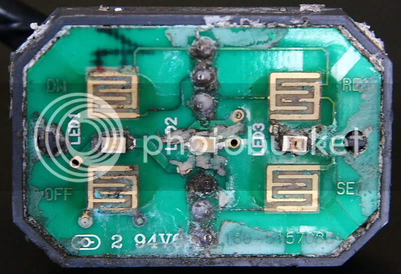
You really do need to see the diagnostic LED flash and follow engine RPM. You also really need to confirm that the key pad is actually working too. The green power LED is not enough. Bikergeek99's key pad:

PCB1.jpg


Who ever sealed this key pad (not BG, it was used) did not use a copper compliant RTV and it greatly contributed to the death of the circuit, complete down to a burned out LED.

I have posted everything that was in my PM to this Forum several times.

 
Last edited by a moderator:
I have fully verified that all things outside of the servo are a-ok.

Sounds like my fix is to change the dip switch setting.

I will ground my b-light relay and change the dip switch setting.

Should be ready for road test maybe tonight or tomorrow depending

on my other 'chores.'

Thanks to all for the quick and comprehensive information, especially

you Ionbeam!

 
And that's that!

CC is back to operational status.

It's been a long time since it's worked, but I do seem to remember in it's final days that

I had to sometimes hit 'set' a few times before it would go.

Today, one tap and it was locked.

Guess I need to see if I can contact the owner of the install page and tell them to update

that switch setting.

Bill, you can have your thread back now!

 
Top