Wicked Webby's Recipe for Great HP and Torque!

Yamaha FJR Motorcycle Forum

Help Support Yamaha FJR Motorcycle Forum:

This site may earn a commission from merchant affiliate links, including eBay, Amazon, and others.
I'm seeing some naysayers here WW. **** it... I appreciate your experimentation and posting of such. I'll be trying it. More air, more horses, I'm there.
Nogage,

Thanks. I am done with the naysayers too!! I have explained it all.. and provided the data. I don't think you will be disappointed. My true only worry about my setup is if the cats can handle +14 without burning up/melting. It is true that the most accurate way to dyno sniff the exhaust would have been to do it before the cats. Time will tell. If I have to punch them out later, I will.

BTW, I figured out a way to do it without dropping the header and cutting them out.

Take care,

WW

 
Thanks WW (I think). I have resisted doing anything to my 05 FJR performancewise except a power commander and a set of Staintune mufflers (which is a world record for me). This has meant that the FJR is never torn down like my other bikes for one performance modification or another. I have a ZX-14 and a radically modified street Harley that both make considerably more HP & TQ than my FJR so I have mostly resisted my normal impulse to modify the **** out of everything in the garage and left the FJR alone (almost). I have looked at the restricted air intake on the FJR for 3 years, knowing there is lost HP there, and resisted the impulse to do something about it so far. Along you come and do the research for me and now I am going to have to try it. It's all you're fault. :yahoo: :yahoo: :yahoo: :clapping: :rolleyes:

 
I'm seeing some naysayers here WW. **** it... I appreciate your experimentation and posting of such. I'll be trying it. More air, more horses, I'm there.
Nogage,

Thanks. I am done with the naysayers too!! I have explained it all.. and provided the data. I don't think you will be disappointed. My true only worry about my setup is if the cats can handle +14 without burning up/melting. It is true that the most accurate way to dyno sniff the exhaust would have been to do it before the cats. Time will tell. If I have to punch them out later, I will.

BTW, I figured out a way to do it without dropping the header and cutting them out.

Take care,

WW

Ohhhhhhh Now I got another damm project.. :yahoo:

I have not cats. I am a dog persons........ That and a complete muzzy setup from the head back...

Do you have any piccies of the filter after the fitting..

Nothing exceeds like excess @!

 
Jstewart and Cdogman,

I too suspected a loss of some hp with the emission restrictions of the air box. I knew this could easily be changed!! As I have shown. I don't have pics of my filters BUT I will pull um and take some this weekend for you all. I have to work all weekend so give me a couple days here. We got a late Spring Snow Storm so I won't be riding until early next week anyways.

Cdog, I suspect you may even be able to find more power with this setup if you do a custom tune with your PWC!! Just speculation... One thing is for sure... Dyno it because thats the only way to really know what you got/getting!!

WW

 
Jstewart and Cdogman,
I too suspected a loss of some hp with the emission restrictions of the air box. I knew this could easily be changed!! As I have shown. I don't have pics of my filters BUT I will pull um and take some this weekend for you all. I have to work all weekend so give me a couple days here. We got a late Spring Snow Storm so I won't be riding until early next week anyways.

Cdog, I suspect you may even be able to find more power with this setup if you do a custom tune with your PWC!! Just speculation... One thing is for sure... Dyno it because thats the only way to really know what you got/getting!!

WW
OK WW the modification is made to the airbox with some variation to what I think you have done. I cut the stock air inlet horn extension off the same as you initially did. I opened up the other side of the airbox to the exact inside diameter of the existing raised flange that holds the stock filter in place on the right side. I found that the stock air inlet cover assembly can be adapted to the other side of the air box so I will order another one to mount on the right side of the airbox with the inlet facing toward the rear of the bike. This modification doubles the stock air inlet area to the airbox and cutting off the stock inlet extension unmasks the left side of the filter . I am using a K&N filter which has a higher air flow capacity so I am going to retain this setup until I can do some testing. I like the stock airbox inlet which Yamaha pointed toward the rear for a good reason and I will duplicate it on the new air inlet to the airbox on the right side. This is a low pressure area area that gets cool air and is the best area to draw inlet air from. Don't know how much testing I will be able to do in the next couple of days as rain is forecast through the weekend. I'll get back next week with my impression after some experimentation with the power commander settings. Let the games begin. :yahoo:
jstewart,

The way you have described.. You change the amount of air intake from 2 square inches to 4 square inches.. My recipe would prolly be way to much fuel for that amount of air... If you read my recipe and instructions you will see that I added close to 50 square inches of air from the stock air box.

WW

WW,

See, I think that is where everyone got confused about your experiments and mods. You went into great detail about cutting off the air horn in the other thread and even showed pictures, etc. but then in this one you chopped up the box much further.

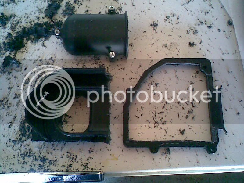
There was one picture (below) that showed the end of the air box in pieces. I think I am correct in assuming that the only part in that picture that was returned to the bike was just the cut-off edge (piece on the right) and then you made a similar chop to the right side end of the box as well?

This was what necessitated you using 2 new flat panel K&N filters. You could no longer use the stock shaped filter as you had nothing to hold it in place anymore. So the flat filters just cover the big open ends of the box, right?

Image022.jpg


WW I may end up where you are now on the intake modifications but I want to take it one step at a time and experiment. I checked my Staintune mufflers and they should be as free flowing as any of the other straight through designs with the restrictors removed. The only difference with the Staintunes is they are perminantly packed with sound deadener. Since this is my all round rider I only want to make a few small incremental changes that remove some of the emissions & inlet noise restrictions Yamaha had to deal with and retune the power commander for the changes. As you have found out small changes can add up. As for setting proper A/F ratios for any modifications, I am looking at various data logging systems to use on the ZX-14 which is set up primarily for drag racing. This tool can also be used on the FJR as it already has a exhaust sensor fitting for the Bosch wide band sensor used on these data logging systems. This should provide a more accurate fuel map for the power commander than tuning on a dyno using an exhaust gas sample from the muffler after the cat. I am not sure how you came up with 2 square inches as the area of the stock air inlet to the air box. Measuring the inner circumfence of the oval inlet extension I cut off (inside circumfence=7 inches) and using the standard math formula for the area of a circle (A=3.14 X the radius squared) I come up with 3.9 sq/inches. Doesn't sound like much but it was sufficent to supply enough air to make 126 HP on my 05 FJR with the stock airbox and a K&N filter. If the K&N filter will pass enough additional air the 7.8 sq inches of inlet area may give me what I want.

 
Last edited by a moderator:
Fred,

Thanks for clearing that up for those that didn't read the entire thread.

Jstewart,

The 2 square is the air inlet hole in the stock cover of the air box door. That oval shaped opening is approximately a 1 inch by 2 inch opening letting air into the box. This setup expands this to nearly 5 inches by 5 inches on both sides(x2 math guy). The volume inside the air box has not changed... Almost 50 sq inches of an open "air" door instead of the 2 sq inches. BTW, I am not using a Power Commander(as previously stated). Even though the cats clean up the unspent fuel.. I could still see a big change in the AFR on the dyno when adding the extra air and adjusting the CO levels.

If anyone can improve on my findings... I welcome it!! PLEASE DO!! And share the info!!! Sharing this informaton makes the FJR a better bike for all!!

WW

 
Fred,Thanks for clearing that up for those that didn't read the entire thread.
NP. But I have to ask, why did you put the ends back on at all? Was that to support the new K&N panel filters?

We haven't seen how the new filters fit into the chopped box yet.

Maybe there is a way to get some kind of filters in there after having removed (and retained) the ends of the box entirely. That way it is 100% reversible at zero cost!! I'm envisioning some sort of a long rectangular filter that seals against the front side of the box, leaving the entire box wide open (but I don't remember what the box looks like inside).

 
Last edited by a moderator:
Thanks WW for all the work on this. Stupid of me, I already had the side panels back on and just measured the extension area I had cut off. At any rate it will be a while before I get to do any testing. It is going to rain here through Tuesday and I have to fly to Los Angeles for business for the rest of next week and won't be back until Sunday night. I had been tempted to do this (adding a 2nd opening on the other side of the airbox) since changing the stock filter over to the K&N over 2 years ago. Because my job eats up so much of my time and I have 2 other bikes which I am always trying something new on I just never got around to it. I am not going to try and get any more from this bike than this fairly simple mod will provide. I just hope it will get me an extra 5 HP while retaining the K&N filter. If you are looking for further improvements pull the airbox, the rubber velosity stacks, the throttle bodys and the rubber adaptors between the TB's and the head. 90% + of the time you will find slight mismatches at the mating points of these components which can be cleaned up with a dremel & sand roll to reduce inlet turbulence and increase performance. Small incremental changes that compliment each other add up. Thanks again for the R&D.

 
Jstewart,

Hey no problem. I have found the more air only helps the FJR!! Let me know when you get to tinkering on your setup!

Fred,

Yes, exactly. Had to come up with a good way to secure the panel style K n N filters. Make sure they had a good air tight fit and could not get sucked out of position under WOT. And I wanted my setup to be done so that I could access both filters from the left side of the box. Pics are coming as soon as this work week ends I get time to pull the filters out. I will take some pics of the filters and the air box itself. I was so anxious to get my bike slapped back together after the dyno that I spaced the whole photo shoot!!

WW

 
It seems to me that the next step is to take this to an aftermarket manufacturer and get a kit out there for sale.

Back in the '70s, Honda made a 500/550 four with a too restrictive airbox/filter design. Someone? came-up with a better idea that improved performance considerably and it was successfully marketed -- to lots of grateful 500/550 riders.

I, personally, don't think my FJR needs any (engine) performance help -- but, maybe alot of others do? :unsure:

 
One more question WW. In doing the barbarian mod did you put a jumper or a 22k resistor from pin 25 to pin 29 of the ECU plug??? I have seen some confusion in different posts concerning the pin numbers and whether to use a jumper or the resistor on model years 04 and up. On another site I found a post this week that said that the Y/R wire in # 23 was moved to pin # 25. This leaves me somewhat confused about the correct procedure for my 05 FJR.

 
jstewart,

You are confusing GenI to GenII. Here is the link to clarify:https://www.fjrtech.com/getdbitem.cfm?item=6

 
Silver I couldn't get anything on the link address. I am assuming my 05 is the gen 2 in the original farkle instructions posted on fjrtech which, if I am reading them correctly, would mean I need to install a jumper or 22K resistor between pins 25 & 29. If there is a later change for the 05 & later FJR's I haven't been able to find it yet.

 
jstewart,

The mod on the '05 is the same as the '04 I believe.

As Written:

The '04 models don't come with wires in pins 29 and 27, so the trick is to simply jumper #25 to #29 as shown above. A plain 16-18 gauge wire can be used, or you may use a 22k ohm resistor, as shown in the photo. Either way works. If you can get to the "CO adjust mode" after doing this mod, then you did it correctly.

Go to this page at the bottom for the 04-05 differences that should clafify for you.

https://www.fjr1300.info/howto/jumper.html

 
Last edited by a moderator:
jstewart,
The mod on the '05 is the same as the '04 I believe.

As Written:

The '04 models don't come with wires in pins 29 and 27, so the trick is to simply jumper #25 to #29 as shown above. A plain 16-18 gauge wire can be used, or you may use a 22k ohm resistor, as shown in the photo. Either way works. If you can get to the "CO adjust mode" after doing this mod, then you did it correctly.

Go to this page at the bottom for the 04-05 differences that should clafify for you.

https://www.fjr1300.info/howto/jumper.html
Thanks 03HiYoSilver,

That is what I was gonna say. Gen II's are 06 on up.

WW

 
Thanks guys. I had the farkle from FJRtech and the second part was posted before the 05's came out concerning the change for the 04 model. I am assuming this is what the author was referring to when he said gen 2 because the wiring was different on the 04 ecu plug from the 03 model. I think of the gen 2 fjr as the 06 & up models like WW's 07. I checked my plug and pin 23,24,25, 27 & 29 have plastic plugs installed. pin 26 has a brn/red wire and pin 28 has a blue/red wire installed. These colors don't match the picture for the gen 2 mod so the color coding on some of the wires also changed in 05. I am assuming WW used the gen 2 method (jumped pin 25 to 29) on his 07 model. I am going to do the same with a 22 K resistor and try it. What really got me confused was a guy on another site posting he had suscessfully done the mod by moving the wire from pin 23 to pin 25 and didn't state what year bike he had. I think he was talking about a gen 1 03 model and he meant pin 27 but typed 23.

 
Outstanding WW. :fans: :fans: :fans: :fans: :fans:

I've done this sort of thing on a few non-fi bikes. Nothing like the rush from that first time the front wheel gets air!

Let's pair this up with Dale's headers. :yahoo:


Latest posts

Top