06 Stalls when put in gear

Yamaha FJR Motorcycle Forum

Help Support Yamaha FJR Motorcycle Forum:

This site may earn a commission from merchant affiliate links, including eBay, Amazon, and others.

S76

Well-known member
Joined
Nov 11, 2005
Messages
1,147
Reaction score
11
Location
Stafford CT
Took the bike out for the first time today. Should have stayed home. Leaving the driveway when I shifted to 2nd the engine died. WT? Stupid sidestand I thought. Cycles the side stand a few times bike started and ran fine. Nervous at this point I rode up and down the road with in pushing distance to home. No further problems. Went and got gas and rode about 3 miles away from home and it died dead. Assuming it was the side stand switch, on the side of the road, I cut the switch wires and twisted them together. Again, starts right up in neutral, neutral light is on, but as soon as I shift to 1st it dies. It will also die when the clutch is in or out when putting it in gear, makes no difference.

The up side is a nice guy stopped, went home to get his trailer and brought me and biotch home. He rides a Victory. I'm going to get him a resturant gift certificate for sure.

I thought I read a thread on this same situation but cannot find it now. Is this a problem with the shift indicator switch in the trans?

:angry2:

 
Found it!

After much head scratching and "Attempting" to read the schematics I finally trace the problem to the combination fuel pump and engine cut off relay. I had no idea where this was, book was no help locating it, and ended up pulling all the plastic including the front cowl. Finally found it, right above the front wheel, between the headlights. Had I known, you could have just reached up there and removed it off its rubber strap mount without taking anything apart. UGH!

Anyway, there are diodes in this relay that the side stand switch and neutral switch signals pass through on their way to the ECU. They provide a ground for the ECU through one of either 2 wires, and without this ground the engine is O.F.F. One of the diodes was open on the side stand leg of that circuit. Relay is P/N 5VK-81950-30-00 for $35. And to top it off it is 70 Degrees and sunny, parts will take 10 days to arrive. Grrr.

And yes Alan, I did have to use the DVM on this one. The screwdriver/shorting things out method wasn't working. LOL

 
Found it!
After much head scratching and "Attempting" to read the schematics I finally trace the problem to the combination fuel pump and engine cut off relay. I had no idea where this was, book was no help locating it, and ended up pulling all the plastic including the front cowl. Finally found it, right above the front wheel, between the headlights. Had I known, you could have just reached up there and removed it off its rubber strap mount without taking anything apart. UGH!

Anyway, there are diodes in this relay that the side stand switch and neutral switch signals pass through on their way to the ECU. They provide a ground for the ECU through one of either 2 wires, and without this ground the engine is O.F.F. One of the diodes was open on the side stand leg of that circuit. Relay is P/N 5VK-81950-30-00 for $35. And to top it off it is 70 Degrees and sunny, parts will take 10 days to arrive. Grrr.

And yes Alan, I did have to use the DVM on this one. The screwdriver/shorting things out method wasn't working. LOL
Damn, that's some good troubleshooting, S76! Congrats on finding it and not having to pay a dealer..

 
Yeah, the neutral switch and the sidestand switch go to that relay, and ONLY that relay. If it doesn't correctly pass what it sees from the switches on through those diodes, then the ECU misreads the switches.

 
In all honesty, it really wasn't all me.

I can read aircraft wiring prints, but I could not read those prints in the manual. A wire goes to a plug and you can't see how it continues. You have to go to Sheet 2, then, maybe you can find it, maybe you can't. I took the prints to work to have one of the Avionics guys try to make sense out of it. He couldn't figure it out either, but he was smart enough to find a trouble shooting procedure for this relay module. And then, being obsessed with the problem and staying up to 3 AM tearing the bike to pieces, I was able to figure it out. Which, like everything else was simple once you knew. The book did show the relay location but pointed to the front of the bike, looking like it was by the battery. It isn't.

Parts will be 10 or more days out I'm sure. In the mean time I am going to put a jumper in by the ECU to ground. That will by pass the diodes and disable the side stand safety feature so I can ride. I won't leave it like that because I do sometimes put it in gear and the safety feature reminds me to stop being a dumba$$. It's a good feature. Plus, having the bypass jumper installed, and then disabled when I get the new parts, should I ever have this problem on the road I can just reconnect the bypass and be on my way.

But a bigger question is why did this happen? That is really bugging me. I haven't seen many, or any, reports of this type of failure. A general trouble shooting proceedure is: "What was the last thing you touched" that's probably it. I did solder all my grounds together and ran multiple additional grounds. If a little does a little good.... and all that, you know. I still need to study the unreadable prints to see if I may have caused this myself. The one thing I did do, that in hind sight (crystal clear) I probably should not have done was to tie the S2 and S5 spiders to the rest of the grounds.

That may have been put too much ground path current through these ECU diode paths. Not sure.

 
Found it!<snip>And yes Alan, I did have to use the DVM on this one. The screwdriver/shorting things out method wasn't working. LOL
Congratulations on the find.

Tell ya what, if we can hook up during the Clam Chowder ride, youse and mes can sit around and use screwdrivers to uncork a few cans of our favorite beverages and swap some electrical war stories :drinks:

 
. . . why did this happen? . . .
You obviously got struck by lighting somewhere.

Those diagrams really aren't that hard, but I don't like them as well as the earlier ones that actually follow the line all the way through. When the wire stops at a connector you have to find the same connector number on the other page and continue from there.

Component location is a ***** sometimes. My '03 has 5 relays under the nose cowl, and the service manual points to the nose cowl, but has them located incorrectly. I had to determine which was which by working all the circuits and listening for clicks.

 
QUOTE (S76 @ Mar 19 2010, 04:53 PM) <{POST_SNAPBACK}>

... A wire goes to a plug and you can't see how it continues. You have to go to Sheet 2, then, maybe you can find it, maybe you can't. ...

Couldn't agree more. I'm a semi-retired electronics engineer and I have a lot of trouble with these diagrams.

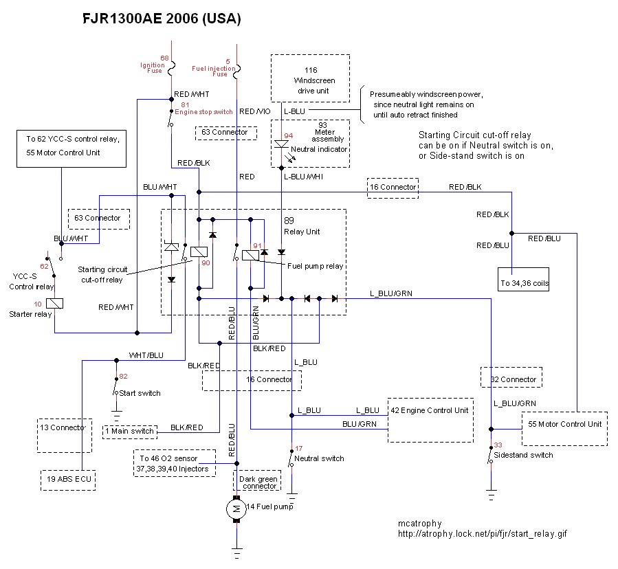
I did make a diagram of the starting interlocking stuff for the YCC-S diagram:

start_relay.jpg


It might help someone with a similar problem; I'd have posted it earlier in this thread, but thought it might confuse the issue because of the YCC-S bits and lack of clutch switch.

QUOTE (S76 @ Mar 19 2010, 04:53 PM) <{POST_SNAPBACK}>

... But a bigger question is why did this happen ...

That may have been put too much ground path current through these ECU diode paths. Not sure.

These diodes can fail very quickly if overloaded. Did you disconnect the battery whilst playing with your earthing? It would be easy to touch something you shouldn't when delving into the loom.

 
Last edited by a moderator:
... A wire goes to a plug and you can't see how it continues. You have to go to Sheet 2, then, maybe you can find it, maybe you can't. ...
Couldn't agree more. I'm a semi-retired electronics engineer and I have a lot of trouble with these diagrams.

I did make a diagram of the starting interlocking stuff for the YCC-S diagram:

start_relay.jpg


It might help someone with a similar problem; I'd have posted it earlier in this thread, but thought it might confuse the issue because of the YCC-S bits and lack of clutch switch.

... But a bigger question is why did this happen ...That may have been put too much ground path current through these ECU diode paths. Not sure.
These diodes can fail very quickly if overloaded. Did you disconnect the battery whilst playing with your earthing? It would be easy to touch something you shouldn't when delving into the loom.

Now that diagram I can read and understand! That's nice.

No I didn't disconnect the battery, nor do I shut off power when doing house wiring. I just figure the jolts and resulting eye twitching are part of the job. Myself, ( and many others) don't understand why I am the way I am, but I am, so I guess I'm just that way. :unsure:

Tonight when I get home from work (at midnight) I'm going to get that bad boy back together with a bypass wire so I can ride tomorrow. Supposed to be 72* and I don't plan on missing it. This weather is better than summer.

Tomorrow's post, more likely than not, will be the tale of how I high sided in a curve because the sidestand was down and I was bleary eyed due to lack of sleep. LOL

 
Just realized another place one of those wires goes through: There's a wire that reads Neutral only, and another that reads neutral or sidestand. That second wire goes through the ignition switch from the relay before it gets to the ECU, so a problem with the second pole of the ignition switch will interrupt it. It's possible for the relay to be OK and the ECU still fail to get the ground from the sidestand switch, if the ignition switch has a problem.

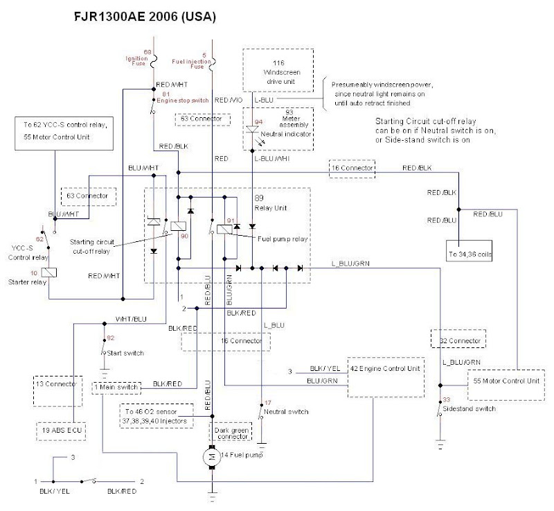
The Black/Red wire in the diagram above (that goes to the ignition switch) becomes a blue/green wire at the switch and continues to the ECU. THAT is where the ECU reads the sidestand. That wire should be 12-ish volts with the sidestand down and ignition on, low volts with the sidestand up and ignition on. Also, his diagram is AE, I think, without the clutch switch. I think on non-AE bikes that wire from the neutral switch to the ECU does not connect there (before the interlock relay) and the clutch lever becomes part of the circuits on the interlock relay. The neutral ground is applied to one side of the clutch switch through the diodes in the interlock relay, and the ECU gets the ground from there. The sidestand-or-neutral ground is applied to the other side of the clutch switch. If I can describe it in terms of mca's diagram, it's like this: That line that comes straight down from relay coil #90, then bends to the right. . . . Break that line and put the clutch switch there. Then take that line from the ECU at the neutral switch and run it to the side of the clutch switch that's connected to the relay 90 coil. The neutral switch goes ONLY to the interlock relay on non AE. I don't know the wire colors for that, though.

But for your specific problem, grounding the blue/green wire at the ECU will bypass the sidestand switch for sure. Grounding the black/red wire at the relay will bypass the sidestand switch as long as the ignition switch is OK. If you ground that and still die going into gear, then you have an ignition switch problem.

The diode network gives the ECU a neutral-only ground reading, and a neutral-or-sidestand ground reading.

EDIT: fixed up mca's diagram to accomodate A vs. AE. I cut that corner under the relay, and put a 1 and a 2 there, and at the bottom left, the 1 and 2 represent those points of that wire. I also cut the wire from the neutral swirch to the ECU, whcih is not in the A wiring, and it's at 3 on the clutch switch area. I also added the wire from the ignition switch to the ECU that carries the sidestand ground, I'm not sure of its color. My 2006 diagram shows it as blue/green, and the wire he shows as blue/green, to the fuel pump relay, I show as blue/yellow.

start_relay%20A.jpg


Last edited by a moderator:
wfooshee,

I can not thank you enough!

I came home last night and was going to install the bypass and start puttting the bike together. I got all wrapped around the axle with those diodes and the circuit through the switch got me confused. So I could not figure out what wire to jumper, and was not sure enought to risk messing up the ECU.

Your post got me heading in the right direction. I did check all the circuits through the key switch and they were good. I rechecked the diodes in the relay assy again and they are definetly open. So I just did what you said and put a ground on the ECU blue/green wire and it works perfect. I made the jumper with a bullet connector in the middle so when the new relay comes in I can just unplug the jumper. I think I'll leave it there so if I ever have a similar problem I can plug in and carry on.

Took most of the day to put the bike back together but I did head out and rode for 3 hours. Bike ran great, new tires felt great, (perfect balance up to 120,) Russel seat felt great. (Except I cannot touch the ground to well at all.)

All in all a great day. Again thanks, I would not have been able to ride today without your post.

Bob

 
" I'm a semi-retired electronics engineer and I have a lot of trouble with these diagrams."

I wish someone with your level of detail and clarity would totally re-write the whole darn service manual. It's the priciest POS I have ever seen. Just a sorry excuse for a service manual.

Good job on the schematic. Maybe you could crank us out one per month? :clapping:

 
Top