johnny80s
Turtle Gears
Joe this looks like it is coming along nicely. The last thing I saw was the bottom plate. This looks like you are in the home stretch. Good luck.


 [SIZE=36pt]-[/SIZE]


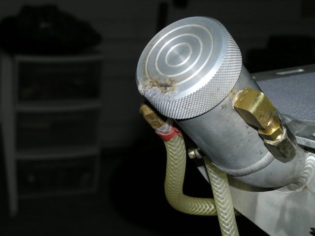
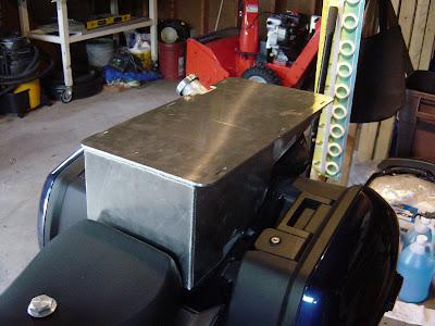
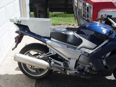
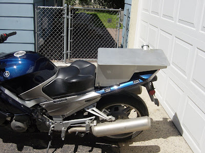
FedEx scale reads 15.05 pounds.Cool!
How much does it weigh, btw?
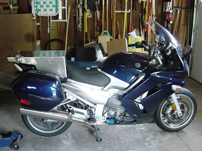
It should be bolted on by the time Shane and I head up to Webby's for the suspension connecting arm install.That is nice looking Joe!! Well done my friend.Looking forward to seeing it up close.
Sounds like a great idea. Let me know what day are you guys scheduled for Webby's...I'll definitely try to get up there for that.It should be bolted on by the time Shane and I head up to Webby's for the suspesion connecting arm install.Maybe the four of us could go out for a burger.
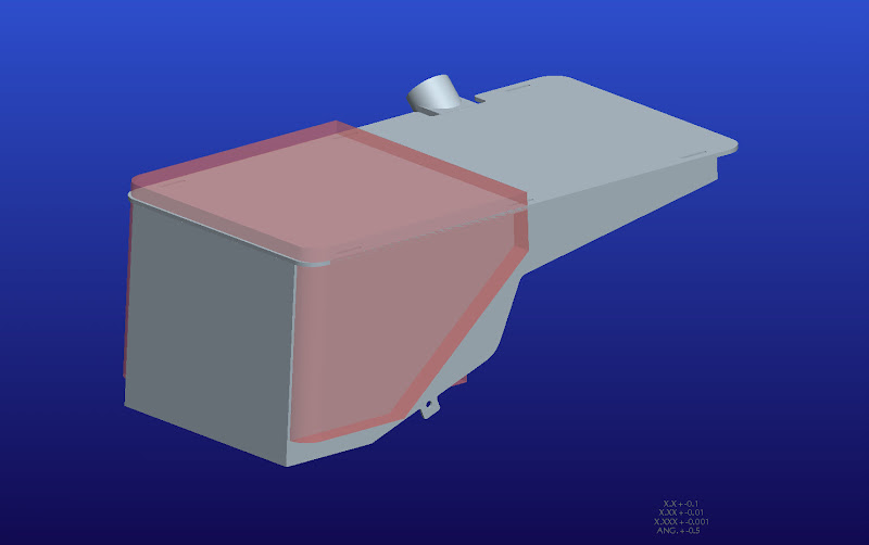
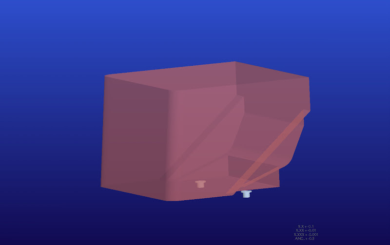

I see what you mean about it not quite looking right in the screen capture, but I think what we're seeing is an optical illusion. I would have to print the JPEG and measure the lines to be sure.Just a quick question: I notice in your CAD rendering that the perspective seems just a little off... the top and bottom planes don't appear correct. Could this adversely affect your computations for true volume? Having watched your fabrication skills here, I know the finished product won't be built like that, but it seems strange that the program isn't displaying correctly.
It would really suck to have a beautiful new tank all ready to go, only to discover it slightly exceeds the IBA maximum!
Don
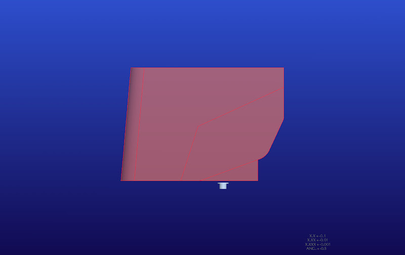
It must be an optical illusion, or something with the screen capture, but it does look like the top is angled 'towards' us more than the bottom.I see what you mean about it not quite looking right in the screen capture, but I think what we're seeing is an optical illusion. I would have to print the JPEG and measure the lines to be sure.Just a quick question: I notice in your CAD rendering that the perspective seems just a little off... the top and bottom planes don't appear correct. Could this adversely affect your computations for true volume? Having watched your fabrication skills here, I know the finished product won't be built like that, but it seems strange that the program isn't displaying correctly.
It would really suck to have a beautiful new tank all ready to go, only to discover it slightly exceeds the IBA maximum!
Don
I'm not worried about the volume working out. The volume on my last tank was calculated correctly by the CAD software, but I forgot to factor in the baffles.
I ordered some of the materials for the tooling today. Once I have that stuff finished, I'll order the aluminum sheet. The only thing I'm farming-out on this one is the welding.
Edit: Also, something that might be contributing to the optical illusion is the front surface of the tank. It slants back at a 5 degree angle.