salan10
Active member
Sorry if I missed this in the thread, but is there a source for new spiders?


You can get them free from anyone that has chopped theirs off.Sorry if I missed this in the thread, but is there a source for new spiders?
")
Any fix that relies on retaining the spiders is less than ideal, in my opinion. The connector is not weather sealed, and even if the overloading due to excess current problem is dealt with, you still have to worry about the possibility of corrosion. I find it preferable to simply cut off the connector and crimp, then seal the crimp with glue-filled style heat shrink tubing. Very secure, waterproof, and there is no loss of functionality since the connectors did not provide separability anyway. The only downside is possibly needing to remove extra stuff to get access to do the crimp. Certainly, fixes that do involve just modifying the spiders are good for people who don't like to mess with factory wiring harness, and 99.9% of the time I would be firmly in that group.Sorry if I missed this in the thread, but is there a source for new spiders?
Assuming your profile is correct, you have a 2003 FJR, or a Gen I. Your FJR is not affected by this problem. You don't have the 'ground spiders' in question. This is only a Gen II (2006+) FJR problem.Sorry if I missed this in the thread, but is there a source for new spiders?
I need to update my profile. I sold my '03 last September and now have an '08. No problem with the wiring harness yet but I want a plan to fix the spider problem the next time I get into the engine area for maintenance. This (long) thread has been very helpful. I am leaning towards simply cutting off the connectors and crimping or soldering the wires.Assuming your profile is correct, you have a 2003 FJR, or a Gen I. Your FJR is not affected by this problem. You don't have the 'ground spiders' in question. This is only a Gen II (2006+) FJR problem.Sorry if I missed this in the thread, but is there a source for new spiders?


For what it's worth, I did a TBS after grounding all the spiders to the chassis, so the bike ran for a total of over 30 mins, with multiple on/off cycles. I also for the very reason you mention and generally because I was messing with the "system" electrics as part of the process of R/R the nose cowl went through all the diAG screens to check for any error codes - there were NO error codes present.[SIZE=14pt]JUST A CAUTION ABOUT ADDING A NEW GROUND WIRE TO SPIDER S3...[/SIZE](The engine management circuit - Spider containing black wires with blue tracer lines near TB)
I just talked to the EE that integrated the Bosch ECM into our vehicle at work and he warned about taking this particular ground back to chassis ground. There shouldn't be a problem bypassing/removing the spider but it is recommended that this circuit finds its ground path SOLELY from the ECM. He said if it was grounded to the chassis, it would probably run okay but certain safety and diagnostic features MIGHT be diabled. He said he wouldn't be surprised if there was an error code stored in memory as a result of adding the wire to the main chassis ground. Maybe one of you guys that have the new ground wire can check for codes (???)
This all made perfect sense to me so I would recommend NOT adding the extra chassis ground wire to S3, since I don't think anyone has reported this one as a problematic one anyway. Better safe than sorry.
With everyone doing their own fix. This will probably cut down on the troubles being had, which in turn will cut down on the reports to the federal saftey site,which in turn will probably hurt the chances of the feds forcing Yamaha into doing something about this problem. Just saying
I tend to agree with you. That is what I was wondering in my previous post, about what color goes were.[SIZE=14pt]JUST A CAUTION ABOUT ADDING A NEW GROUND WIRE TO SPIDER S3...[/SIZE](The engine management circuit - Spider containing black wires with blue tracer lines near TB)
I just talked to the EE that integrated the Bosch ECM into our vehicle at work and he warned about taking this particular ground back to chassis ground. There shouldn't be a problem bypassing/removing the spider but it is recommended that this circuit finds its ground path SOLELY from the ECM. He said if it was grounded to the chassis, it would probably run okay but certain safety and diagnostic features MIGHT be diabled. He said he wouldn't be surprised if there was an error code stored in memory as a result of adding the wire to the main chassis ground. Maybe one of you guys that have the new ground wire can check for codes (???)
This all made perfect sense to me so I would recommend NOT adding the extra chassis ground wire to S3, since I don't think anyone has reported this one as a problematic one anyway. Better safe than sorry.
RZ350Drum roll please...
<snip>
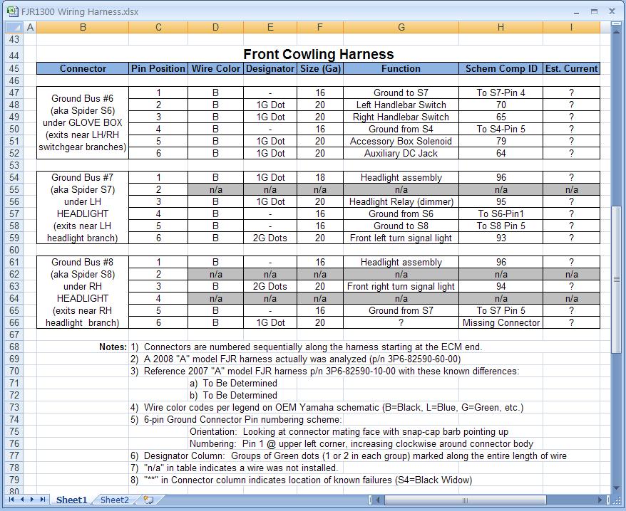
If I end up needing to fix anything on my bike before Yamaha does something about this, I still do NOT plan to do anything to S2 or S5 other than maybe improving the spider connections and weatherproofing. I will encourage everyone else to do the same (Brodie - I hope you're listening if you intend to put some hardware together for the other owners). Depending on what we (as a group) find out about the peak current flow through the wires in S1, S3, S4, S6, S7 and S8, extra grounds may be needed at those spiders.
If I ever get to the Right coast, we will have to share one together. :drinks: My treat![SIZE=12pt]Somebody owes me a beer! [/SIZE] :lol:
Now that I have a little more time, I can elaborate on the discussion I had with the EE (electrical engineer) to pass along all the information. He mentioned that on the Bosch ECM we use at work, information is being monitored and used for internal processing on these ground lines. He went on to say that with certain feedback data, the engine can be put into a "limp-home" mode to protect itself by running at a reduced HP, if it is found to be outside of a certain range. Now, the one huge difference I noticed is that the Bosch ECM circuit utilizes a separate ground wire for EACH sensor, while the Yamaha wiring bunches them together and feeds them into the ECM on a single terminal. I have no idea how they could get useful feedback data through that single combined terminal, but I'm sure those Yamaha folks are smarter than me.[SIZE=14pt]JUST A CAUTION ABOUT ADDING A NEW GROUND WIRE TO SPIDER S2...[/SIZE](The engine management circuit - Spider containing black wires with blue tracer lines near TB)
I just talked to the EE that integrated the Bosch ECM into our vehicle at work and he warned about taking this particular ground back to chassis ground. There shouldn't be a problem bypassing/removing the spider but it is recommended that this circuit finds its ground path SOLELY from the ECM. He said if it was grounded to the chassis, it would probably run okay but certain safety and diagnostic features MIGHT be diabled. He said he wouldn't be surprised if there was an error code stored in memory as a result of adding the wire to the main chassis ground. Maybe one of you guys that have the new ground wire can check for codes (???)
This all made perfect sense to me so I would recommend NOT adding the extra chassis ground wire to S2 (ECM circuit), since I don't think anyone has reported this one as a problematic one anyway. Better safe than sorry.
Careful now - I've been known to ride a long way to get a free beer! :lol:RZ350
If I ever get to the Right coast, we will have to share one together. :drinks: My treat![SIZE=12pt]Somebody owes me a beer! [/SIZE] :lol:
Brodie
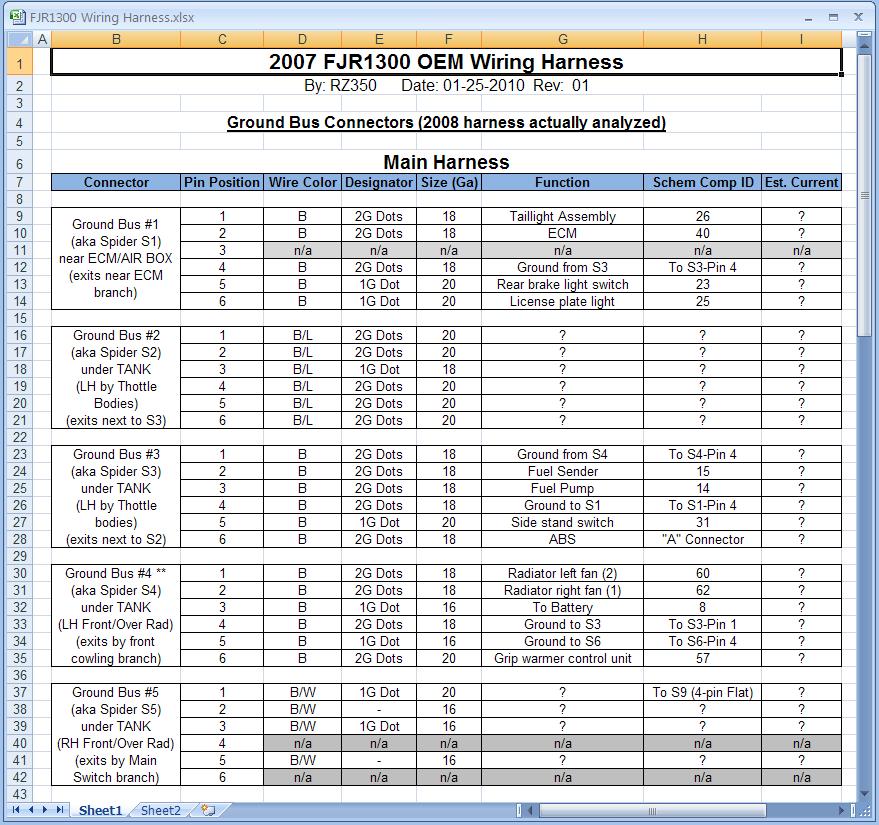
A couple more points to make on this...[SIZE=12pt]My guess, at this point, is either S4-Pin3 (Batt connection), S4-Pin4 (total ground feed from rear of the bike), or S4-Pin5 (total ground feed from the front of the bike) are the BURNERS. Of course there could be others, but these 3 terminals are handling the most current in the ground bus yet their spider spade connectors are the same size as the rest.[/SIZE]
BrodieRZ350Drum roll please...
<snip>
If I end up needing to fix anything on my bike before Yamaha does something about this, I still do NOT plan to do anything to S2 or S5 other than maybe improving the spider connections and weatherproofing. I will encourage everyone else to do the same (Brodie - I hope you're listening if you intend to put some hardware together for the other owners). Depending on what we (as a group) find out about the peak current flow through the wires in S1, S3, S4, S6, S7 and S8, extra grounds may be needed at those spiders.
Yes, I am very interested in the research you gentlemen are doing, I am taking notes. I was going to tie all 8 connectors together with 1 harness and lead it back to the battery negative terminal. With the new findings, it looks more like just tie the high amp. connectors with this method, and just service the other 2 with dielectric grease, seal them off and be done with them. My first post on this subject was a question concerning a ground loop situation brought about by tying all the grounding connectors together. Although it may not produce a true ground loop, it looks like my concerns about causing secondary damage may be valid after all.
I haven't made up my mind which way to go yet, I'm still waiting for supplies with which to build my first prototype. I hope to have something built in a couple of weeks. My goal is to provide something basic enough to fit in for anyone who's willing to lift his fuel tank and remove some tupperware.
Yes I do plan to use the mating female half of the connector in place of the spider and black cover. The 6 pins will join into 1 pigtail shortly after exiting the connector half. I also want to stress that if the Yamaha ground spiders have melted and have damage to the wires, they need to be repaired first before plugging in my harness.
If I ever get to the Right coast, we will have to share one together. :drinks: My treat![SIZE=12pt]Somebody owes me a beer! [/SIZE] :lol:
Brodie
but a Captain & Coke is OK. Not all bad is coming from this, hopefully we can all meet someday and go for a ride.I agree with the separate ground wire suggestion you have for Brodie's kit - much easier to install and it gives the owner the ability to install one at a time at their leisure. Good one.Brodie
Good to see your watching. I like your idea of the 6-1 plug, but making them all on one main wire back to chassis (in series) will be harder on you and the person installing it. I was thinking of each plug being separate with 2 or 3 feet of oh say 14 ga wire, that could go to chassis. Then a person could do just one, or all 6 B spiders. Most people won't want to take apart the dash pod, and we may only need one of them on the S4 or BLACK WIDOW SPIDER. What do ya think ?
RZ350
I think your on to something about the Bosh sender grnds being all separate and using them for feed back. Being that the Yamaha (B/L) spider or ECU spider is all together I don't see how they are using it for feed back. I think they may be keeping it separate from the others because they don't want any feed back going to ECU. If the B/L spider was tied to the B spiders it all may work fine until there was a short to grnd some were in the bike, then it may fry the ECU by back feeding it. I think the same may apply to the B/W spider, because that meter is very delicate.