UselessPickles
Making Grand Canyon replicas from air boxes...
Here's where I tapped into the brake wires:So, can someone point me to where the brown brake wire is?
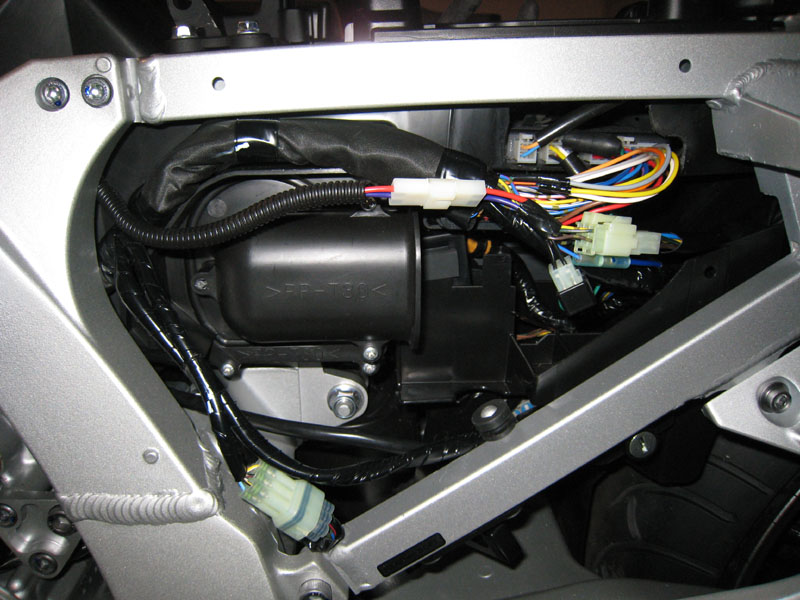
You can see the purple and red AVCC wires heading up to the front of my bike through that plastic tube. I added a 2-wire connector to those wires so that it's not permanently attached (can be removed for maintenance if necessary). To the right of my two-wire connector is where I soldered my connections, which is just to the left of a stock 6-wire connector. Those 6 wires are the the tail wiring (signals, brakes, etc). The wire colors are different on the two sides of that connector. I believe most people tap into the wires on the right side of that stock connector, up in the tail area somewhere. That's probably where you'll find the brown wire.
If in doubt (which you seem to be), test all 6 of those wires yourself by sticking needles/pins through the insulation to the wire and touching a multimeter to the needles/pins to find which one gets 12V when the brake is engaged.

") Ion correctly is pointing out that your errant voltages are not in the wire I indicated, that resistor is in the tach signal.
Ion correctly is pointing out that your errant voltages are not in the wire I indicated, that resistor is in the tach signal.