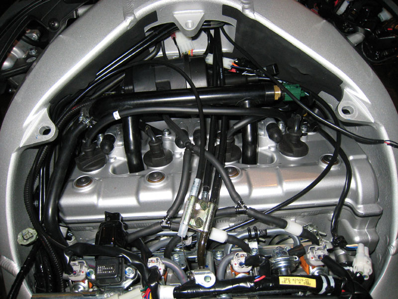
Installing cruise control this weekend...

Yamaha FJR Motorcycle Forum

Help Support Yamaha FJR Motorcycle Forum:

This site may earn a commission from merchant affiliate links, including eBay, Amazon, and others.
extrememarine - thanks for the suggestion - i may take a look at that although I can't figure out how you pulled the wire out. I thought they were 'crimped' into those pins...

Ok, Update - donuts and kolaches were great...

Tab is drilled, but the button head touched the cable! Crap!

So, I grabbed the dremel and ground off some of the head - all good now!

Oh yeah, did the throttle spring unwind-1-turn mod while I was in there...

 
Last edited by a moderator:
Well, I have the servo and vacuum canister under the seat, vauum lines run, fuel rail back on, etc.

Tomorrow comes the elctrical... :)

Those little caps where you hook up the vacuum lines are fun to get off... I didn't want to yank them off with the needle nose, so I got a screw driver and was helping them off while I wiggled them off with the other hand... 1 off, 2 off, 3 off, 4 whoops! scredriver slips off and jabs me in cuticle of the thumb! Holy Cow! Glad the wife and kids weren't around! I immediately resorted to my 1st aid training - paper towel and duct tape.... For those keeping score at home, that is: Me 0, FJR 2 ...

Thanks for the help guys!

 
Last edited by a moderator:
Wiring questions:

  1. Based on a post by Wfooshee, it sounds like the servo red wire should tie in to the brake brown wire if I choose not to go directly to the battery. Correct?
  2. If the red/orange wire needs a switched source, could it also tie in to the brake brown wire along with the servo red wire?
  3. I understand frame grounds are not ideal, but was wondering if there was anything other than the battery that would provide an acceptable ground. If I have a fuse block that is grounded to the battery, could I use that instead (at least for the servo)? Just curious mainly.
  4. I plan to add a brake relay - better now than later I think. Based on this post (https://www.fjrforum.com/forum//index.php?showtopic=105411&st=0&p=432485entry432485), does this look correct?
    • relay #30 to servo purple
    • relay #85 & #87a to ground
    • realy #86 & #87 to brake yellow

 
Last edited by a moderator:
Still not done with the wiring... :( Trying to do it right, so things are slow going; plus, only had 3 hours available to work on it today....

Maybe tomorrow...

Weather was 81 and clear too...

 
Wiring questions:
  1. Based on a post by Wfooshee, it sounds like the servo red wire should tie in to the brake brown wire if I choose not to go directly to the battery. Correct?
  2. If the red/orange wire needs a switched source, could it also tie in to the brake brown wire along with the servo red wire?
  3. I understand frame grounds are not ideal, but was wondering if there was anything other than the battery that would provide an acceptable ground. If I have a fuse block that is grounded to the battery, could I use that instead (at least for the servo)? Just curious mainly.
  4. I plan to add a brake relay - better now than later I think. Based on this post (https://www.fjrforum.com/forum//index.php?showtopic=105411&st=0&p=432485entry432485), does this look correct?
    • relay #30 to servo purple
    • relay #85 & #87a to ground
    • realy #86 & #87 to brake yellow

The servo red wire must go to the brake wire, not the battery. It's not "it should go there if you choose not to go to the battery." The battery is not a choice. Yes, the red wire is for a 12-volt source, but getting it from the brake light wire tells the cruise that the brake light circuit is working. It's conceivable to have a situation where for the fuse for the brake light is blown. If you run the servo red wire to the battery, the servo will not release when you hit the brakes if there's not power on the brake light wire. By using that as its 12-volt source it knows the brake light works. If the fuse is blown and the servo gets its 12 volts there (as it should) it will not set a speed. By far the safer alternative!

Similarly, do not use the brake light wire as a switched source for the orange wire from the keypad. If you don't have a fuse block with a switch output, use the blue wires for the bike's running lights as a switched source.

I grounded my servo to the battery. Not too hard to get the black wire up there.

 
Last edited by a moderator:
Wiring questions:
  1. Based on a post by Wfooshee, it sounds like the servo red wire should tie in to the brake brown wire if I choose not to go directly to the battery. Correct?
  2. If the red/orange wire needs a switched source, could it also tie in to the brake brown wire along with the servo red wire?
  3. I understand frame grounds are not ideal, but was wondering if there was anything other than the battery that would provide an acceptable ground. If I have a fuse block that is grounded to the battery, could I use that instead (at least for the servo)? Just curious mainly.
  4. I plan to add a brake relay - better now than later I think. Based on this post (https://www.fjrforum.com/forum//index.php?showtopic=105411&st=0&p=432485entry432485), does this look correct?
    • relay #30 to servo purple
    • relay #85 & #87a to ground
    • realy #86 & #87 to brake yellow

The servo red wire must go to the brake wire, not the battery. It's not "it should go there if you choose not to go to the battery." The battery is not a choice. Yes, the red wire is for a 12-volt source, but getting it from the brake light wire tells the cruise that the brake light circuit is working. It's conceivable to have a situation where for the fuse for the brake light is blown. If you run the servo red wire to the battery, the servo will not release when you hit the brakes if there's not power on the brake light wire. By using that as its 12-volt source it knows the brake light works. If the fuse is blown and the servo gets its 12 volts there (as it should) it will not set a speed. By far the safer alternative!

Similarly, do not use the brake light wire as a switched source for the orange wire from the keypad. If you don't have a fuse block with a switch output, use the blue wires for the bike's running lights as a switched source.

I grounded my servo to the battery. Not too hard to get the black wire up there.
Thanks wfooshee!

I should have remembered that - I think you had explained that red wire placement/brake safety to someone else also. Sorry, to many posts, they are running together....

I have an EasternBeaver fuse box going in also, so I'll hook in there.

I ran the servo and brake relay ground wires last night up to the battery...

I should be able to finish up today - just have to run the wires up to the control pad connector and the blue wire hookup and put her back together!

This has been extremely educational - it would be more fun if the weather wasn't so nice... ;)

 
Last edited by a moderator:
Well, i think I am done - still taking applications for the test pilot position though... ;)

Finally got all the wiring done - I have a bit of a rats nest to clean up this winter, but that should be easy. Liquid tape is messy, but looks like it would be effective. SPent 30-40 minutes traking down where there was no power to to control pad from the new fuse block - coincidentally, there was no power to fuse block, but that fact was lost on me... Yep, no master fuse in the fuse block power - d'oh!

Will finish buttoning her up tomorrow after a buddy comes by and does a throttle body synch ....

 
Well, i think I am done - still taking applications for the test pilot position though... ;)
Finally got all the wiring done - I have a bit of a rats nest to clean up this winter, but that should be easy. Liquid tape is messy, but looks like it would be effective. SPent 30-40 minutes traking down where there was no power to to control pad from the new fuse block - coincidentally, there was no power to fuse block, but that fact was lost on me... Yep, no master fuse in the fuse block power - d'oh!

Will finish buttoning her up tomorrow after a buddy comes by and does a throttle body synch ....
I have an Eastern Beaver fuse block and AVCC on the bench. Getting ready for the install starting tomorrow. Where did you locate the two?
Hi Roger

I put my Eastern Beaver in the back where the rear two most rubber straps are.

I put the servo under the drivers seat. Probably at some point though I will move it up front over the engine (I am sure you have read about those installs) - I didn't this time 'cause I didn't feel like messing with removing the coolant pipe.

Good luck on the installs - as you probably already know, there is a TON of info here and the guys are extremely helpful...

 
Need some help troubleshooting, please...

Situation: Cruise won't set, accel, etc.; control pad does light and control pad indicator light does show on when On is pressed and off when OFF is pressed.

I had attempted to wire in a brake relay just in case I wanted to do something with the taillights in the future - I have completely removed the relay.

When I try the short LED diagnostics in the book I get

  • turn on - LED lights
  • Press Resume - LED turns off; press again and LED goes on/off
  • Press Set - Same as Resume
  • Press the brake(s) - LED turns off then on when brake is released
 
Need some help troubleshooting, please...
Situation: Cruise won't set, accel, etc.; control pad does light and control pad indicator light does show on when On is pressed and off when OFF is pressed.

I had attempted to wire in a brake relay just in case I wanted to do something with the taillights in the future - I have completely removed the relay.

When I try the short LED diagnostics in the book I get

  • turn on - LED lights
  • Press Resume - LED turns off; press again and LED goes on/off
  • Press Set - Same as Resume
  • Press the brake(s) - LED turns off then on when brake is released

Hm, I had the same basic thing (though I never tried the brake lights thing) on my audiovox, and was told that it was likely corroded/wet connections.

And I've not taken the time to look.

 
I gotta ask -- are you trying this with the motorcycle on the center stand? If yes, it ain't gonna work.

The only way to test the cruise is on the road, or on a chassis dyno. The cruise computer expects the rear wheel to be mechanically loaded with weight and inertia, the gain of the servo needs this loading for correct response. If there is no loading on the rear wheel it reacts to speed commands so fast that the cruise computer recognizes it as an error condition and will not try to control speed.

If you are trying this on the road and it won't set speed the most common problem is on the brake wire. If you have a volt meter, now is the time to use it.

The next thing to check is that you have vacuum at the servo, a finger test on the vacuum hose right at the servo should be sufficient.

 
I gotta ask -- are you trying this with the motorcycle on the center stand? If yes, it ain't gonna work.
The only way to test the cruise is on the road, or on a chassis dyno. The cruise computer expects the rear wheel to be mechanically loaded with weight and inertia, the gain of the servo needs this loading for correct response. If there is no loading on the rear wheel it reacts to speed commands so fast that the cruise computer recognizes it as an error condition and will not try to control speed.

If you are trying this on the road and it won't set speed the most common problem is on the brake wire. If you have a volt meter, now is the time to use it.

The next thing to check is that you have vacuum at the servo, a finger test on the vacuum hose right at the servo should be sufficient.

Somehow I knew you would ask that Ionbeam :) -- no, testing on the road...

I checked the purple wire at the server w/ the key and the bike not running. Something like 0.116 volts. With the brake it was 11.6 volts.

Sounds like I have a problem with the way I hooked up the vacuum - almost bet I put the check valves in wrong...

Good tips!

 
Last edited by a moderator:
I put the servo under the drivers seat. Probably at some point though I will move it up front over the engine (I am sure you have read about those installs) - I didn't this time 'cause I didn't feel like messing with removing the coolant pipe.
Good luck on the installs - as you probably already know, there is a TON of info here and the guys are extremely helpful...
Where the heck will this thing fit under the tank?? Is there some pics of that out there? I have the servo and the fuse box under the seat, it's tight but so far it fits.

Hope you get yours working.

Good Luck!!

 
Where the heck will this thing fit under the tank?? Is there some pics of that out there?
Read about it here (I also have links in that post to additional references I used during my install): https://www.fjrforum.com/forum/index.php?showtopic=114094

servo_and_vacuum_lines_redone.jpg


Hang in there Shawn! I really want to see this relay for the AVCC with a Kisan tailblazer combo workout as I'm going to install the same set up this winter. Thanks for the updates.

 
Something like 0.116 volts.
The servo doesn't like anything besides zero. Something is wrong, if you put the relay in you should see zero on this reading and 12+ on the other, IIRC.

P.S. Roger123, here is another possibility for a mounting location: do the old clickaroo. It's possible to get the servo in there without taking the whole bike apart as I did, a forum search would turn that up or send me a pm.

 
Last edited by a moderator:
Something like 0.116 volts.
The servo doesn't like anything besides zero. Something is wrong, if you put the relay in you should see zero on this reading and 12+ on the other, IIRC.

P.S. Roger123, here is another possibility for a mounting location: do the old clickaroo. It's possible to get the servo in there without taking the whole bike apart as I did, a forum search would turn that up or send me a pm.
Thanks v65 ...

I removed the whole relay from the circuit since I wasn't really needing it and thought it would simplify my troubleshooting...

I have double checked my solder joints for the brake yellow and brake brown and they look good to me.

I went through and checked the various (servo) pin/wire voltages per the installation manual (key on, engine off):

  • black - always continuity to ground - GOOD
  • red - always + 12 VDC - BAD +0.113 VDC at server and at brown wire solder point!
  • brown - + 12 VDC with ignition and cruise control on - GOOD
  • brown - 0 VDC with ignition switch or cruise control switch off - GOOD
  • purple - + 12 VDC when brake pedal is pressed - GOOD
  • purple - 0 VDC when brake pedal is released - BAD +0.113 VDC and at yellow wire solder point.
  • green - GOOD
  • yellow - GOOD

My brakes, and lights, all function normally, so I don't understand the readings I am getting - especially the one off the brown wire.

Additionally, I just checked the vacuum at the servo - seems to be plenty of suction to hold the hose to my finger. However, the idle is too high (~1,800rpm), so I may have an issue with one of the vacuum lines (i used all 4).

I appreciate everyone's help, but I am about to the end of my rope - it won't take much more of this before I rip this thing out...

PS - you guys watching this debacle, don't let it scare you... Undoubtedly this mess is of my own doing. It really shouldn't be this hard, I am just not knowledgeable enough to dig my way out ...

 
Last edited by a moderator:
So, can someone point me to where the brown brake wire is?

I assumed it was in the harness running along the left side (with the yellow & blue, green, & black) and that si where I tapped. However, that is in fact the left turn signal! that would explain the lack of 12 volts...

Edit:

Is this where the elusive brown wire is?

PB030002.jpg


Last edited by a moderator:
Top