sparky3008
Finally got my collarbone fixed!!!
- Joined
- Jul 11, 2005
- Messages
- 1,122
- Reaction score
- 1

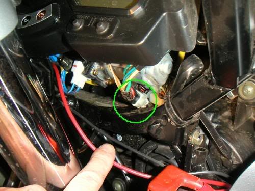
The terminal I circled in red. What are they 2?


1. Fuse blocks: I fuse the main link to the PdB with a max load (20 amps or 30 amps depending on the ga of the wire back to the battery). I then use in-line fuses between the PdB and the device connected to it (they usually come with their own any way)....since you don't use a fuse block just power strips do you use a fuse in line to each of your farkles?
On the link to the auto-retract site. I don't see where they make the jumper that you show you use. The FJR info site looks like they just disconnect the connector and leave it as such. Did I mis something?


You circled something in red? care to make the width of the line bigger or pick a color that us chromatically-challenged viewers can see? :huh:The terminal I circled in red. What are they 2?


Yep. They didn't pull it from the harness. It's tucked in there pretty tightly, but when removed, is the item in photo #1 above. I thought I covered that in the write up, so went back and double-checked. Yep. It says (right after the link to their tech page),
In this picture it looks like what is being disconnected doesn't just look like a jumper. Is the picture just deceiving?
Since relay grounds aren't as critical as something like a Power Commander 3, I tend to run them to a nearby chassis ground so the ground wire doesn't need to be routed through a bunch of the bike (and the total length of wire is shorter).I do have one question though. If you use a relay and run the ground wire from the realy to the block wouldn't you have 1 less ground lead available. I the picture from Mixed up Mitch it looks as if he has the same amount of positive and negatives. Does that mean he ran his ground from the relay to something else?
I took an electronics course on computers years ago that involved using oscilloscopes, capacitors and resistors to measure frequenies and resistance and such.I'm one of those "Like to Know How It Works" type people but never got into electronics. Can anyone point me to a good introductory electronics book useful in my future farkling? Thanks.
Are you referring to the windshield auto retract loop?I disconnected the green-circled harness...
Yesterday while digging there to find that jumper I concluded that on my '05, there's no power running through it. I clipped the jumper, reinstalled it and no matter which one I probed, no juice.
I ended up using the turn signal +12 to power my relay. Anyone know if they changed that jumper on '05 models?
I would add this, car stereo's with amplifiers and subwoofer's would be one place where understanding ohm's law in regards to ohm's and impedence will come in extremely handy so as to not blow up a $$$ amp. (Don't ask me how I knowI took an electronics course on computers years ago that involved using oscilloscopes, capacitors and resistors to measure frequenies and resistance and such.I'm one of those "Like to Know How It Works" type people but never got into electronics. Can anyone point me to a good introductory electronics book useful in my future farkling? Thanks.
Anyway this type of "electronics" has been of almost no use to me as I never went into repairing circuit boards or anything as a hoppy or professionally. Some of the programmers I work with like to repair old computers as a hoppy and use these types of instruments and knowledge.
Working on your bike it is really nothing more than installing a 12v positive and negative system. I had a brain fart really understanding relays but I don't know why as I use to work on big printing presses that used relays all the time but I was over thinking it. For only a few items such as the upgraded horns which draw more power than the stock switch was designed for are relays necessary.
For most stuff you will do it is as simple as running positive to positive and ground to ground and maybe putting in a fuse do not burn out a device.
Nothing really anymore complicated than that really...
 )
)I read this statement then I look at the name -- Sparky -- Coincidence? I think not… :shock: :rolf:one place where understanding ohm's law in regards to ohm's and impedence will come in extremely handy so as to not blow up a $$$ amp. (Don't ask me how I now
That's right. Funny thing is doing commercial or residencial electrical work has no relation to car audio other than the fact that electrons and protons are involvedI read this statement then I look at the name -- Sparky -- Coincidence? I think not… :shock: :rolf:one place where understanding ohm's law in regards to ohm's and impedence will come in extremely handy so as to not blow up a $$$ amp. (Don't ask me how I now
Alan
Protons are involved but they are not what is moving. Electrons are moving from atom to atom. As the atoms wants to be balanced with the same amount of protons and electrons and we disrupted that the atom is constantly trying to acquire balance. The loss of an electron and the ion is now positively charged it is an attractant for another electron to come along and attach itself.Protons aren't involved. You'd need to overcome the Strong nuclear force to liberate them.
I think I read that somewhere :dribble:
You have to test both sides of the loop once it'd clipped in half. Do it with the ignition on and with the ignition off. You might be surprised which is hot and when.I disconnected the green-circled harness...
Yesterday while digging there to find that jumper I concluded that on my '05, there's no power running through it. I clipped the jumper, reinstalled it and no matter which one I probed, no juice.
I ended up using the turn signal +12 to power my relay. Anyone know if they changed that jumper on '05 models?
Enter your email address to join: