Brodie
Darksider #16 - and Proud of it !
- Joined
- Sep 17, 2006
- Messages
- 1,453
- Reaction score
- 538
While some were out and galavanting about the valley of death, I took advantage of the nice weather this weekend and opened up my bike for servicing. Lately I've been getting a lot of overtime but not much chance to work on the beast.
The following pictures are the start of my Grounding Harness project. The goal is to have a true "plug & play" harness that requires minimal effort to graft onto the bike, and is fully reversible if necessary. Based on the excellent work from RZ350, Road Runner, and other FJRForum members, I was able to come up with a plan to address all the ground spyders. Two of the spyders tie into the bike's electronics. I opted to just inject them with silicon dielectric grease and reassemble them. They only handle low current and are in no danger of burning out. The other six handle nearly all of the bike's electrical load back to the battery. The largest gage wire in the ground circuit is approximately 16 gage. Although the wire size is sufficient to carry the load, the connectors tend to get weathered and corroded. When this happens they are in danger of an electrical thermal runaway. Corrosion begets resistance which causes heat and more resistance and so on. The end result of this thermal cycle is not pretty. There have been way too many owners stranded by this weak link in our otherwise fine motorcycle.
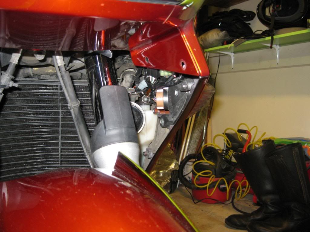
These first 2 pictures show the extent of the tupperware removal...
Remove the seats, fuel tank, tee bar, heat shield and left side panel.
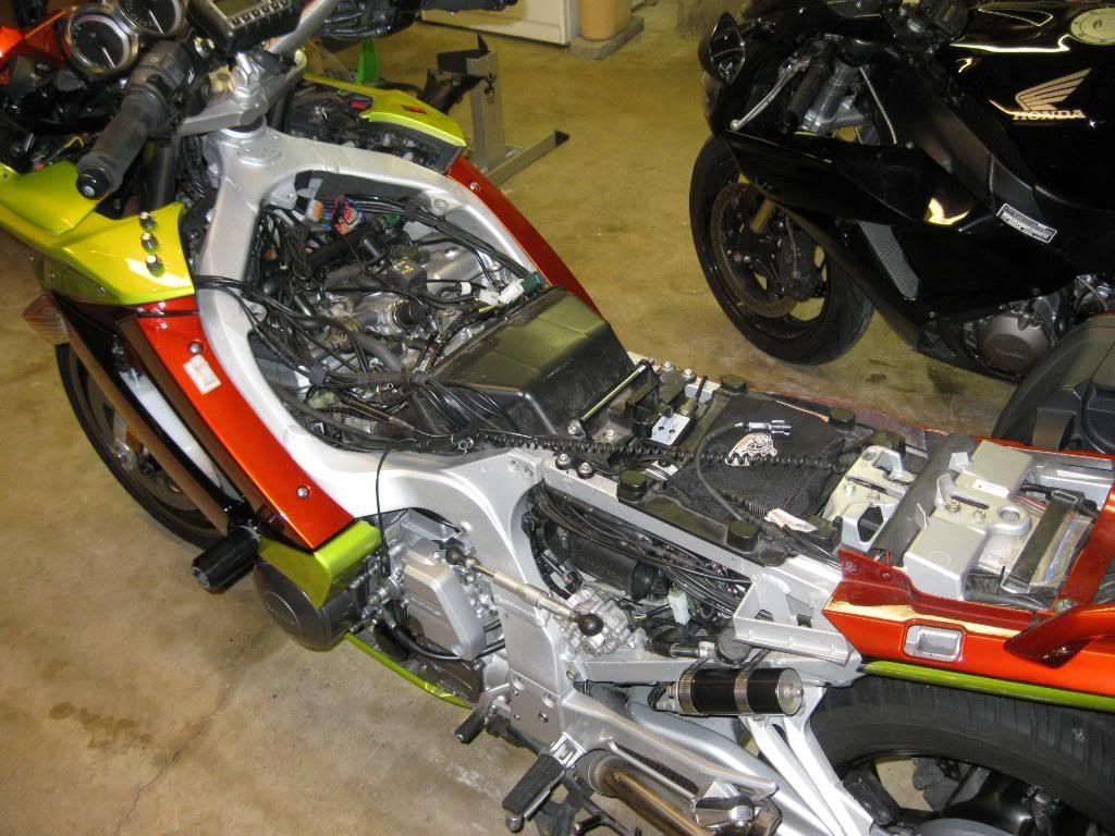
Remove the left inner fender panel.
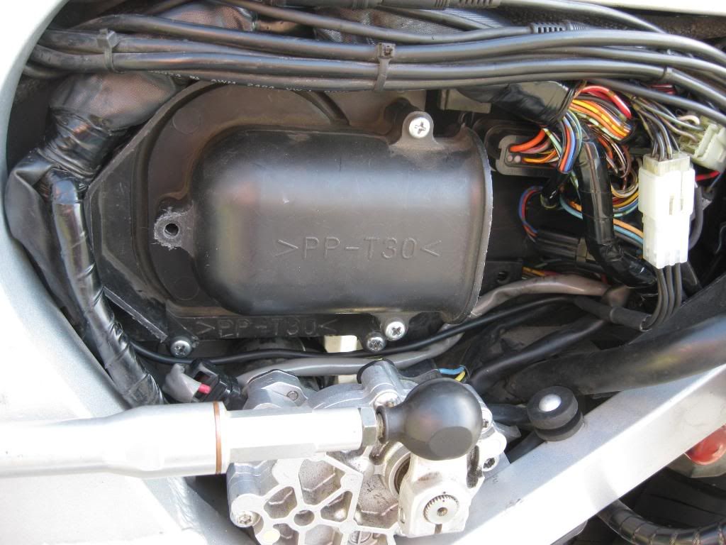
The S1 spyder lives next to the air filter. Remove the cover over the wire bundle. Note the 1 into 6 wire along the bottom leading up to the bright white connector on the far right. This is the female half of the connectors that yamaha uses for the ground spyders. Remove the black plastic cap and spyder from Yamaha's connector, inject it with dielectric grease, and connect my Grounding Harness to it.
The next 2 spyders, S2 and S3 live next to the fuel rail to hose hookup. Service the black/blue wired spyder with dielectric grease and reassemble it. Tuck it away for safe keeping. It is not a part of my Grounding Harness. The other black wired spyder gets dielectric greased and plugged in.
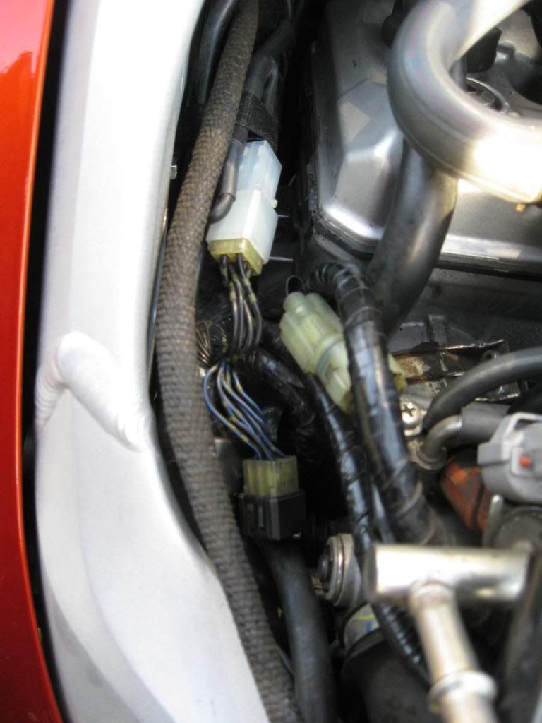
This is the S4 BLACK WIDOW spyder that seems to give so many of our owners grief. It lives above the engine at the far left front in front of the coolant water pipe. Check it closely for heat damage. Dielectric grease it and plug it in. Note... the spyder on the far right with the black/white wires is also not a part of my Grounding harness. Service it with dielectric grease and reassemble it.
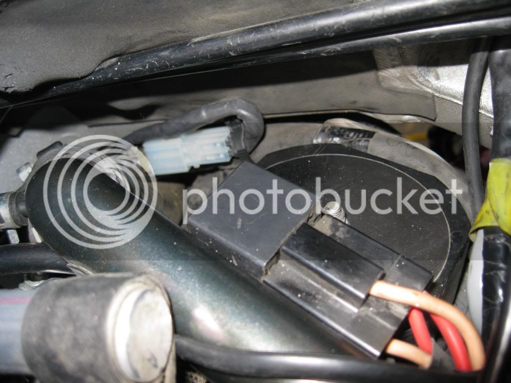
We are now in the lower front left fairing behind the left turn signal. This is another spyder (S6) with a bad reputation. Check it closely for heat damage, Dielectric grease it up and plug it in.
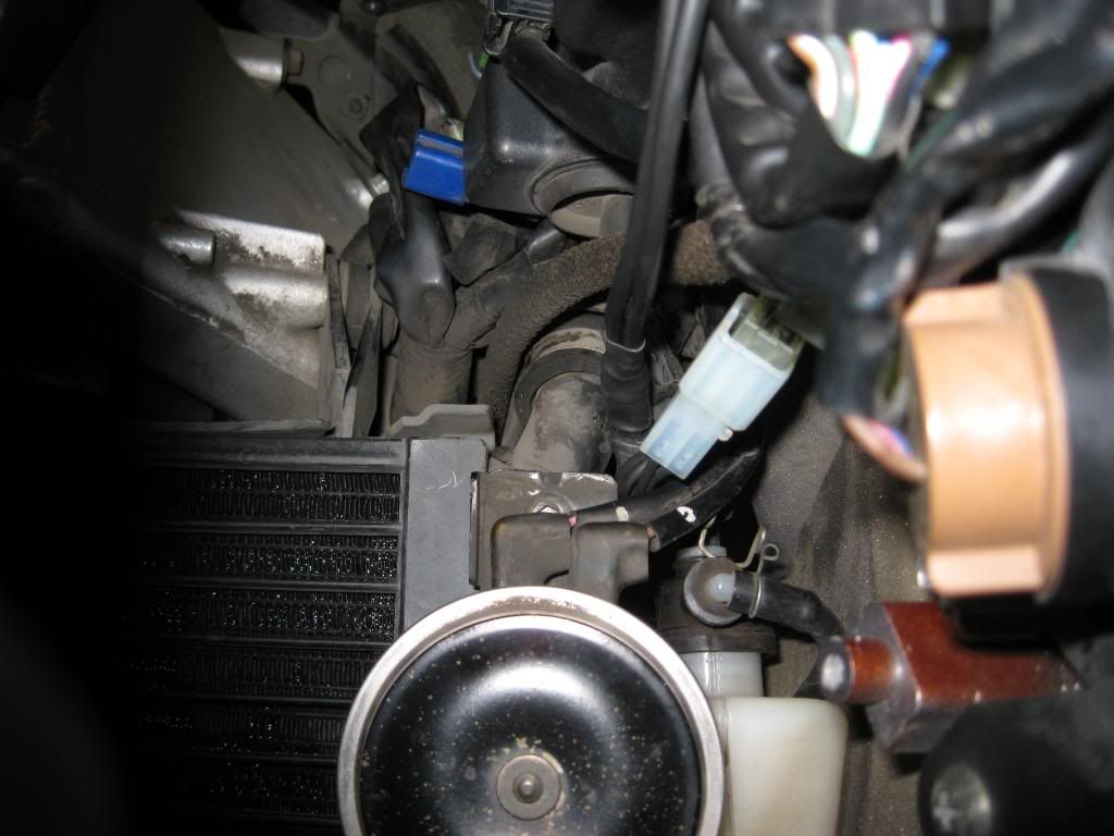
This S7 spyder is located behind the headlight high beam relay behind the service panel in front of the storage compartment. Dielectric grease it and plug it in. This was a b**ch to get to.
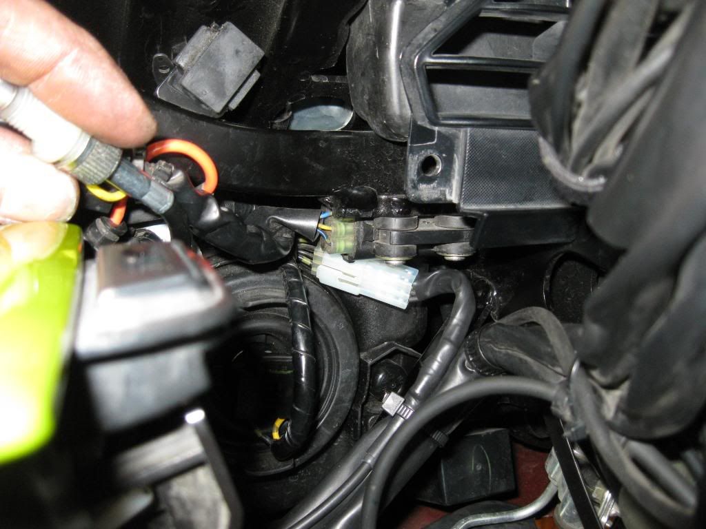
This S8 spyder is located behind the right side access panel in front of the battery. It's buried deep and is a royal b**ch to get to (worse than the other one). Take heart, it's the last one.
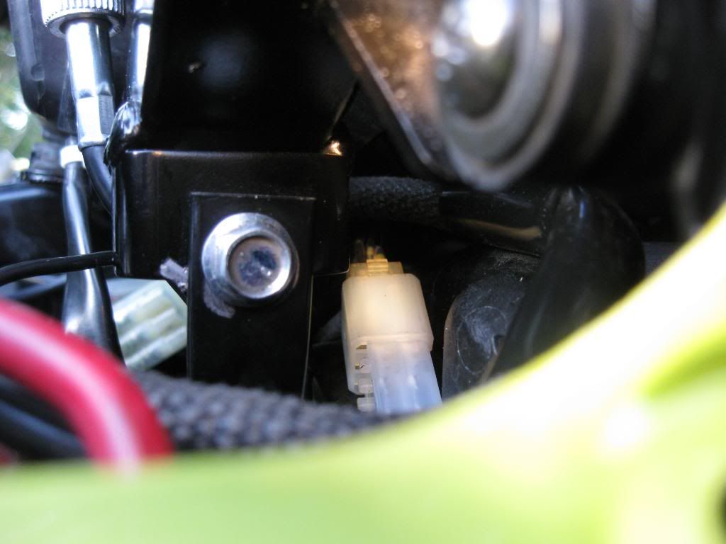
I end up at the negative battery terminal. I know, there is a lot of things hooked up here. Good thing I have a slightly longer bolt tying it all together.
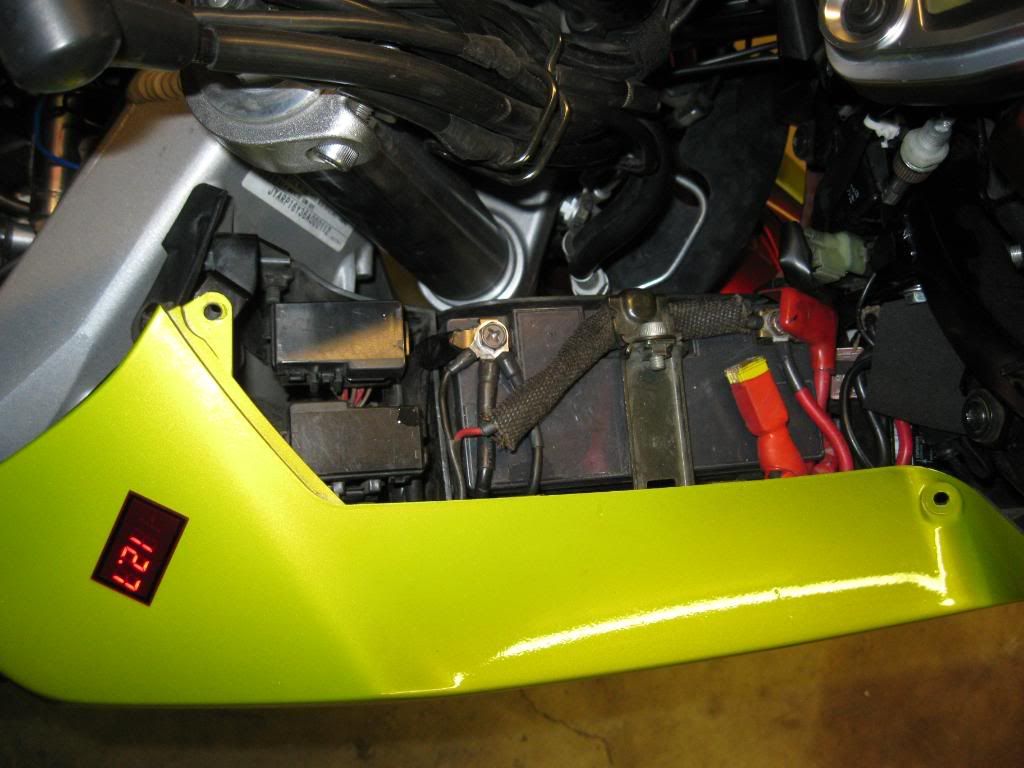
Mission accomplished!
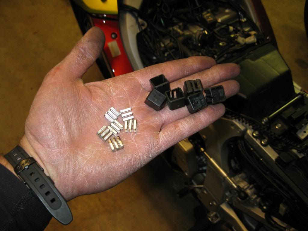
I got it back together around 9pm and took it for a spin. I noticed no difference in the Datel readout - wasn't expecting any; however, I know the Black Widow has been put under control. :yahoo:
I will be ordering wire and supplies in bulk this next week. My goal is to have 15 Grounding Harnesses done by month's end. If there is enough demand I will go into production just like I did with my Ignition Relay Harness. I have not set a price yet, however by buying in bulk I can keep my costs down and will pass that savings on. I will not take orders yet, I want to have product in hand before that happens.
All and all I'd say I had a good weekend.
Brodie
The following pictures are the start of my Grounding Harness project. The goal is to have a true "plug & play" harness that requires minimal effort to graft onto the bike, and is fully reversible if necessary. Based on the excellent work from RZ350, Road Runner, and other FJRForum members, I was able to come up with a plan to address all the ground spyders. Two of the spyders tie into the bike's electronics. I opted to just inject them with silicon dielectric grease and reassemble them. They only handle low current and are in no danger of burning out. The other six handle nearly all of the bike's electrical load back to the battery. The largest gage wire in the ground circuit is approximately 16 gage. Although the wire size is sufficient to carry the load, the connectors tend to get weathered and corroded. When this happens they are in danger of an electrical thermal runaway. Corrosion begets resistance which causes heat and more resistance and so on. The end result of this thermal cycle is not pretty. There have been way too many owners stranded by this weak link in our otherwise fine motorcycle.
These first 2 pictures show the extent of the tupperware removal...
Remove the seats, fuel tank, tee bar, heat shield and left side panel.

Remove the left inner fender panel.

The S1 spyder lives next to the air filter. Remove the cover over the wire bundle. Note the 1 into 6 wire along the bottom leading up to the bright white connector on the far right. This is the female half of the connectors that yamaha uses for the ground spyders. Remove the black plastic cap and spyder from Yamaha's connector, inject it with dielectric grease, and connect my Grounding Harness to it.

The next 2 spyders, S2 and S3 live next to the fuel rail to hose hookup. Service the black/blue wired spyder with dielectric grease and reassemble it. Tuck it away for safe keeping. It is not a part of my Grounding Harness. The other black wired spyder gets dielectric greased and plugged in.

This is the S4 BLACK WIDOW spyder that seems to give so many of our owners grief. It lives above the engine at the far left front in front of the coolant water pipe. Check it closely for heat damage. Dielectric grease it and plug it in. Note... the spyder on the far right with the black/white wires is also not a part of my Grounding harness. Service it with dielectric grease and reassemble it.

We are now in the lower front left fairing behind the left turn signal. This is another spyder (S6) with a bad reputation. Check it closely for heat damage, Dielectric grease it up and plug it in.

This S7 spyder is located behind the headlight high beam relay behind the service panel in front of the storage compartment. Dielectric grease it and plug it in. This was a b**ch to get to.

This S8 spyder is located behind the right side access panel in front of the battery. It's buried deep and is a royal b**ch to get to (worse than the other one). Take heart, it's the last one.

I end up at the negative battery terminal. I know, there is a lot of things hooked up here. Good thing I have a slightly longer bolt tying it all together.

Mission accomplished!

I got it back together around 9pm and took it for a spin. I noticed no difference in the Datel readout - wasn't expecting any; however, I know the Black Widow has been put under control. :yahoo:
I will be ordering wire and supplies in bulk this next week. My goal is to have 15 Grounding Harnesses done by month's end. If there is enough demand I will go into production just like I did with my Ignition Relay Harness. I have not set a price yet, however by buying in bulk I can keep my costs down and will pass that savings on. I will not take orders yet, I want to have product in hand before that happens.
All and all I'd say I had a good weekend.
Brodie
Last edited by a moderator:


