Ok yeah I'll check those things again tonight when I get home from work. If the relay is bad, do you think there is a feasible way to just simply bypass the relay altogether? I'm going to start looking through the wiring diag. again here in a few and see what else that relay is responsible for...Correctly wired, the clutch switch cannot kill the bike, only inhibit starting. That shows that it's either a bad relay, or wired incorrectly.
In neutral, the clutch and sidestand switches won't do anything at the relay. In gear, the sidestand needs to be grounded (wires connected) and the clutch switch needs to be connected.
Ya know, it's almost sounding like wires are going to the wrong connector pins at the relay if it isn't the relay itself. Get an ohmmeter onto that connector and test the pins like I outlined earlier. Looking at the end of the connector, with the notch at the top, the lower left pin should ground when the sidestand wires are connected. In your build, it wouldn't hurt to just run that wire straight to ground to force the "sidestand up" reading, since you'll never use the sidestand. The third pin (sky blue wire) should ground when it's in neutral. The second and fourth pins should connect to each other (not to ground) when the clutch is depressed (clutch switch closed.)
If those are right, then the relay is bad. The sidestand switch and the neutral switch are connected to the relay directly, and the relay passes those connection on to the ECU, which sounds like where the breakdown is. That could explain the neutral light failure, even though the bike seems to know when it's in neutral as far as starting goes.
You are using an out of date browser. It may not display this or other websites correctly.
You should upgrade or use an alternative browser.
You should upgrade or use an alternative browser.
Reverse Trike
- Thread starter Nitrotate
- Start date


Help Support Yamaha FJR Motorcycle Forum:
This site may earn a commission from merchant affiliate
links, including eBay, Amazon, and others.
wfooshee
O, Woe is me!!
I may have found it. Did you use the bike's ignition switch, or just rig up a toggle for ignition on?
The main switch on the bike is double-pole. The first pole does what you'd expect, applies 12 volts to the fuse block for the switched circuits. That's the red hot wire being connected to a brown/blue wire, which carries 12 volts to the fuses.
The other pole connects the neutral-or-sidestand ground signal from the starter cutoff relay to the ECU. If you don't have that connection made (Blue/yellow connects to White/blue at the ignition switch) then the ECU thinks the sidestand is down while in gear, it can't see the neutral switch or the sidestand switch.
The reason the bike starts with the clutch pulled, then dies when you release it, is (I think) that the neutral switch grounds one side of the clutch switch through a diode in the starter cutoff relay, and while the switch is engaged, the ECU sees that ground, but loses it when you release the clutch. I may be cross-eyed from this wiring diagram, but I think that explains your symptoms. If you aren't connecting both circuits with your ignition switch, the ECU can't see the sidestand switch and shuts off the motor.
I'd drawn up a way to remove the starter cutoff relay and jumper the connector to put the clutch switch in series with the starter button. The effect would be that the bike didn't care whether it was in gear or not, but you would have to depress the clutch pedal to engage the starter, much like any modern car. I still couldn't get that sidestand switch ground signal to the ECU without cutting a wire and grounding it somewhere else, and I wasn't sure that was a good idea.
BTW, the reason your neutral light was fubar'd even though the bike seems to know it's in neutral might be due to the damage your donor has at the front. The 12 volts for the neutral light comes from the windshield drive mechanism, of all places, probably a convenience in wiring harness design. Your neutral switch is grounding OK, and passing what it's supposed to into the cutoff relay and beyond, but there's no 12 volts at the other side of the bulb if the windshield drive is all busted-ass.
Last edited by a moderator:
I may have found it. Did you use the bike's ignition switch, or just rig up a toggle for ignition on? I used the bike's original switch.
The main switch on the bike is double-pole. The first pole does what you'd expect, applies 12 volts to the fuse block for the switched circuits. That's the red hot wire being connected to a brown/blue wire, which carries 12 volts to the fuses.
The other pole connects the neutral-or-sidestand ground signal from the starter cutoff relay to the ECU. If you don't have that connection made (Blue/yellow connects to White/blue at the ignition switch) then the ECU thinks the sidestand is down while in gear, it can't see the neutral switch or the sidestand switch. So I assume I could maybe cut those two and connect them together outside of the switch then right?
The reason the bike starts with the clutch pulled, then dies when you release it, is (I think) that the neutral switch grounds one side of the clutch switch through a diode in the starter cutoff relay, and while the switch is engaged, the ECU sees that ground, but loses it when you release the clutch. I may be cross-eyed from this wiring diagram, but I think that explains your symptoms. If you aren't connecting both circuits with your ignition switch, the ECU can't see the sidestand switch and shuts off the motor.
I'd drawn up a way to remove the starter cutoff relay and jumper the connector to put the clutch switch in series with the starter button. The effect would be that the bike didn't care whether it was in gear or not, but you would have to depress the clutch pedal to engage the starter, much like any modern car. I still couldn't get that sidestand switch ground signal to the ECU without cutting a wire and grounding it somewhere else, and I wasn't sure that was a good idea. I'm willing to give it a try if you want to explain or send a pic of what you drew up... I'm going to take some pics of my setup so you can see what I'm working with too.
BTW, the reason your neutral light was fubar'd even though the bike seems to know it's in neutral might be due to the damage your donor has at the front. The 12 volts for the neutral light comes from the windshield drive mechanism, of all places, probably a convenience in wiring harness design. Your neutral switch is grounding OK, and passing what it's supposed to into the cutoff relay and beyond, but there's no 12 volts at the other side of the bulb if the windshield drive is all busted-ass. Good thought and I didn't know about the 12v coming from the drive mech. I don't have the drive motor connected at all anymore so maybe I'll dig through and try to find the correct wire to supply 12v to and then the light should work.
I was feeling crappy yesterday so still didn't make it out to the garage but I should be able to tonight. I replied to you within your text above ^
wfooshee
O, Woe is me!!
I wouldn't. That grounds the ECU line even with the ignition off, and I'm not sure that's a Good Thing. There's probably a reason Yamaha interrupted that line with the ignition switch.So I assume I could maybe cut those two and connect them together outside of the switch then right?
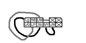
Go ahead and test the connections to the relay connector as I outlined before. The pin labelled Sb in the diagram below (ignore the jumpers I've drawn for now) should ground with the neutral switch. The pin labelled L/G should be grounded by the sidestand switch. If you keep the relay, just ground that wire and forget about the switch or its wires at the connector. The pins labelled L/Y and B/Y should connect when the clutch switch is engaged.
EDIT: Doesn't apply, because I stupidly didn't verify on my own bike before posting, and didn't consider the fact that the ECU actually applies voltage to these wires. My process here is therefore incorrect, and I've corrected it in another post below. I also missed a line on the wiring diagram, and between those two facts my jumper setup to bypass the relay doesn't apply at all. Nobody use this, OK?

If you decide to bypass the starter cutoff relay, here's what you should do:
Cut the blue/yellow wire at the ignition switch, leaving enough wire on the switch to reach a ground point. Use an ohmmeter to verify that it connects to the white/blue wire which the ignition is on. If that's OK, then ground the stub of the blue/yellow that's on the ignition switch. That will force the sidestand-up signal at the ECU.
THEN . . . . .
Unplug the connector from the starter cutoff relay, and jumper it like so:
Leave the connector off of the relay. The jumpers off the two L/W pins will put the clutch switch in series with the starter button so you have to press the clutch pedal before the starter will work. The other jumper passes the neutral switch ground into the meter panel for the neutral light. Use any switched 12V, like the running lights, on the brown/red wire from the meter panel to energize the neutral light if you don't want to reconnect the windshield drive.
The blue/yellow wire HAS to be cut and grounded at the ignition switch for the jumpers to work, because the blue/yellow is how the sidestand switch gets to the ECU. Grounding it forces the ECU to read "sidestand up." Grounding that wire without cutting it would energize the starter with just the clutch, probably not a good idea.
You need to make sure the white/blue wire from the ignition switch gets to the ECU intact, or the bike will still shut off when you declutch or go into gear, if it even starts after doing the jumpers. If the ECU doesn't see that ground when it's supposed to, the bike won't run.
Obviously, test everything out with the rear off the ground. I'd hate it if I missed something and you smashed your project through the wall and into your living room or something. . . . .
Last edited by a moderator:
wfooshee
O, Woe is me!!
I just hope the wire colors are the same on yours. . I'm reading an '03 service manual.
I'm reading an '03 service manual.


$197.39
$209.99
Milwaukee Leather SH1408 Men's Sporty Crossover Vented Black Motorcycle Leather Scooter Jacket - Large
Amazon.com


$19.99
MOREOK Winter Gloves -10°F 3M Thinsulate Warm Gloves Bike Gloves Cycling Gloves for Driving/Cycling/Running/Hiking-Black-L
MOREOK-US (Ships from USA)

$86.99
Edwards Oil Change Kit fits 2003-2020 Yamaha FJR1300 Sport Touring (Full Synthetic)
Edwards Motorsports & RV's


$14.99
$17.99
MELASA Fleece Lined Winter Cycling Beanie with Holes for Glasses - For Men, Women
HNXCHUANG


$64.99
Edwards Oil Change Kit fits 2003-2020 Yamaha FJR1300 Sport Touring
Edwards Motorsports & RV's


$72.99
$89.99
Electric Heated Underwear Set Fleece Lined Thermal Body Suit Men Winter APP Control Temperature Motorcycle Top Pants (Black, XL)
linzhoushiyangzhengmaoyiyouxiangongsi


$64.60
$68.00
WILD HEART Waterproof Motorcycle Duffel Bag PVC500D Double-bottom With Rope Straps and Inner Pocket 40L 66L 100L for Kayaking, Camping, Boating,Motorcycle
ZHONGSHAN WILD FRUIT OUTDOOR


$159.99
FLAVOR Men Brown Leather Motorcycle Jacket with Removable Hood (Large (US standard), Brown)
FLAVOR Leather


LOL yeah I'm looking at a diagram from online but it doesn't indicate the year so I hope so too... could have a 3-way cluster f%&@...!I just hope the wire colors are the same on yours. .
I'll figure it out eventually...
Ok so I'm either looking at the wrong relay/connector or the wire colors are not the same... There are more wires than your diagram shows and the "empty" spaces are in a different location from your diagram also.
Here's the relay I'm looking at:

Here's one side of the connector so you can see the wires:

Here's the same connector turned over:

Here's the two sidestand wires under the tank:

Here's the two Clutch wires:

Here's the front where I ran the ign. switch and other controls to:

Here's the relay I'm looking at:
Here's one side of the connector so you can see the wires:
Here's the same connector turned over:
Here's the two sidestand wires under the tank:
Here's the two Clutch wires:
Here's the front where I ran the ign. switch and other controls to:
wfooshee
O, Woe is me!!
That, my friend, is different. I have a 2003 and a 2006 service manual, and I thought the 2003 was more representative of the later Gen-I bikes. That relay you show is the starter cutoff relay for '04 and '05 according to the Yamaha parts fiche. The connector you picture is what I see as the connector on my '06 diagram, but the '06 relay is a different part number, so I can't say my '06 wiring diagram is gonna be any help. I'll dig around a bit and see what I can match up to your pics.
Last edited by a moderator:
wfooshee
O, Woe is me!!
OK. The difference is that your relay unit actually houses two relays on completely independant circuits. The starter cutoff relay is in there, as is the fuel pump relay. The only thing they share is the 12 volt supply for the coils. The starter cutoff relay circuit itself is identical to my '03.
Also, I missed one connection yesterday which renders my jumper setup incorrect, and I missed the fact the the ECU applies power to the lines on the clutch switch, it does not simply read them for grounds. That was stupid of me, just reading the diagram instead of getting the voltmeter out.
So, some corrections for which wires to test on the connector. I "borrowed" your pictures.
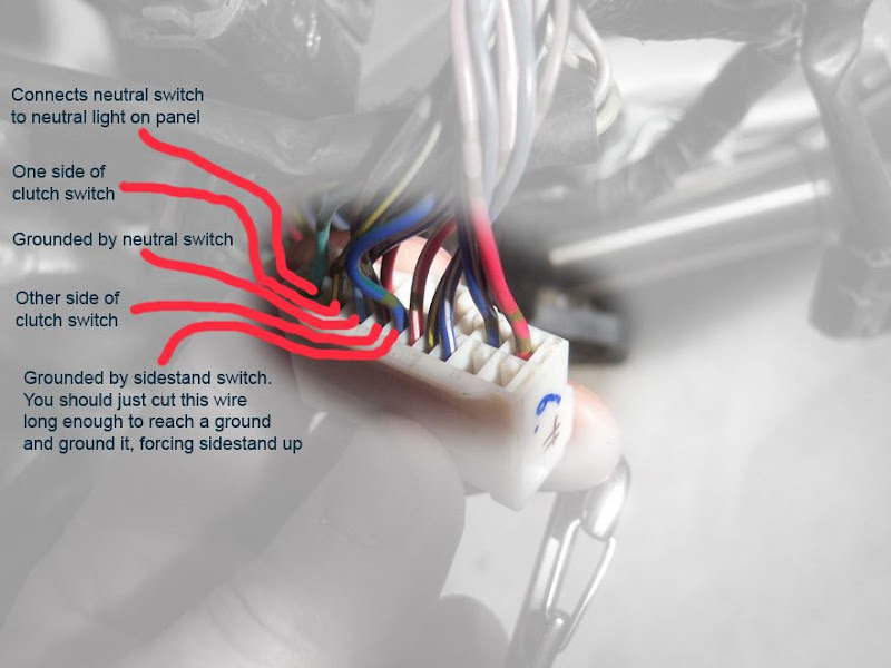
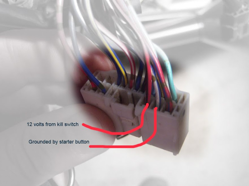
The second pic is not so important for testing since we know the starter works, it's just informative, I guess. The first picture labels what should be happening at the wires. The one labelled "Connects neutral switch to neutral light" is actually dead when the connector is unplugged. Unplug the connector and use an ohmmeter to test the conditions I labelled. You should see that the neutral switch wire grounds when the bike is in neutral, and you should see the sidestand switch wire ground when the sidestand switch wires are connected. (That wire is the one you should just cut and ground directly.) Then connect the ohmmeter across the two clutch wires, and you should see the clutch switch work with the pedal: it's normally open, it closes when the clutch is operated. It's possible, if the pinout is different from '05 to '06, that I've got one of the clutch wires wrong on my labels, but I hope not.
Now connect the relay, switch your meter to volts on a scale good for 12 volts. Turn the ignition on, do not start. Ground the black lead of your voltmeter, and at the clutch switch wires, look for these conditions:
One wire (I think blue/yellow) will show 12 volts if the bike is in gear and the sidestand is down (wires disconnected.) The other one (black/yellow) show 12 volts when the bike's in gear. This is what's controlled by the network of diodes in the relay assembly.
If that all tests out correctly, then listen for the relay clicks again: kill switch on, ignition on, bike not running, sidestand switch wires not connected (or wire at the connector not grounded.) Moving the shifter between first and neutral should click the relay. If so, move on. Put the bike in first. Operate the clutch. You should not get any clicking. Now connect the sidestand switch wires, or just ground the wire from the relay connector, and operate the clutch again. Now it should click with the clutch switch closed.
I sure wish someone near you with an '04 or '05 could ride by and lend you the relay box long enough to see if it acts different with their relay. That would let you know for sure if it's the relay or your wiring. I think those circuits are actually the same in Gen-II bikes, but the relay part number is different. The '04 and '05 both use the part number in your picture.
BTW, you can tap any switched 12-volt wire and connect it to the brown/red wire at the meter connector to enable the neutral light.
Also, I missed one connection yesterday which renders my jumper setup incorrect, and I missed the fact the the ECU applies power to the lines on the clutch switch, it does not simply read them for grounds. That was stupid of me, just reading the diagram instead of getting the voltmeter out.
So, some corrections for which wires to test on the connector. I "borrowed" your pictures.
The second pic is not so important for testing since we know the starter works, it's just informative, I guess. The first picture labels what should be happening at the wires. The one labelled "Connects neutral switch to neutral light" is actually dead when the connector is unplugged. Unplug the connector and use an ohmmeter to test the conditions I labelled. You should see that the neutral switch wire grounds when the bike is in neutral, and you should see the sidestand switch wire ground when the sidestand switch wires are connected. (That wire is the one you should just cut and ground directly.) Then connect the ohmmeter across the two clutch wires, and you should see the clutch switch work with the pedal: it's normally open, it closes when the clutch is operated. It's possible, if the pinout is different from '05 to '06, that I've got one of the clutch wires wrong on my labels, but I hope not.
Now connect the relay, switch your meter to volts on a scale good for 12 volts. Turn the ignition on, do not start. Ground the black lead of your voltmeter, and at the clutch switch wires, look for these conditions:
One wire (I think blue/yellow) will show 12 volts if the bike is in gear and the sidestand is down (wires disconnected.) The other one (black/yellow) show 12 volts when the bike's in gear. This is what's controlled by the network of diodes in the relay assembly.
If that all tests out correctly, then listen for the relay clicks again: kill switch on, ignition on, bike not running, sidestand switch wires not connected (or wire at the connector not grounded.) Moving the shifter between first and neutral should click the relay. If so, move on. Put the bike in first. Operate the clutch. You should not get any clicking. Now connect the sidestand switch wires, or just ground the wire from the relay connector, and operate the clutch again. Now it should click with the clutch switch closed.
I sure wish someone near you with an '04 or '05 could ride by and lend you the relay box long enough to see if it acts different with their relay. That would let you know for sure if it's the relay or your wiring. I think those circuits are actually the same in Gen-II bikes, but the relay part number is different. The '04 and '05 both use the part number in your picture.
BTW, you can tap any switched 12-volt wire and connect it to the brown/red wire at the meter connector to enable the neutral light.
Last edited by a moderator:
OK. The difference is that your relay unit actually houses two relays on completely independant circuits. The starter cutoff relay is in there, as is the fuel pump relay. The only thing they share is the 12 volt supply for the coils. The starter cutoff relay circuit itself is identical to my '03.
Also, I missed one connection yesterday which renders my jumper setup incorrect, and I missed the fact the the ECU applies power to the lines on the clutch switch, it does not simply read them for grounds. That was stupid of me, just reading the diagram instead of getting the voltmeter out.
So, some corrections for which wires to test on the connector. I "borrowed" your pictures.
The second pic is not so important for testing since we know the starter works, it's just informative, I guess. The first picture labels what should be happening at the wires. The one labelled "Connects neutral switch to neutral light" is actually dead when the connector is unplugged. Unplug the connector and use an ohmmeter to test the conditions I labelled. You should see that the neutral switch wire grounds when the bike is in neutral, and you should see the sidestand switch wire ground when the sidestand switch wires are connected. (That wire is the one you should just cut and ground directly.) Then connect the ohmmeter across the two clutch wires, and you should see the clutch switch work with the pedal: it's normally open, it closes when the clutch is operated. It's possible, if the pinout is different from '05 to '06, that I've got one of the clutch wires wrong on my labels, but I hope not.
Now connect the relay, switch your meter to volts on a scale good for 12 volts. Turn the ignition on, do not start. Ground the black lead of your voltmeter, and at the clutch switch wires, look for these conditions:
One wire (I think blue/yellow) will show 12 volts if the bike is in gear and the sidestand is down (wires disconnected.) The other one (black/yellow) show 12 volts when the bike's in gear. This is what's controlled by the network of diodes in the relay assembly.
If that all tests out correctly, then listen for the relay clicks again: kill switch on, ignition on, bike not running, sidestand switch wires not connected (or wire at the connector not grounded.) Moving the shifter between first and neutral should click the relay. If so, move on. Put the bike in first. Operate the clutch. You should not get any clicking. Now connect the sidestand switch wires, or just ground the wire from the relay connector, and operate the clutch again. Now it should click with the clutch switch closed.
I sure wish someone near you with an '04 or '05 could ride by and lend you the relay box long enough to see if it acts different with their relay. That would let you know for sure if it's the relay or your wiring. I think those circuits are actually the same in Gen-II bikes, but the relay part number is different. The '04 and '05 both use the part number in your picture.
BTW, you can tap any switched 12-volt wire and connect it to the brown/red wire at the meter connector to enable the neutral light.
Alright so I think I've narrowed it down finally with your help. So everything tested out correctly accept for mainly one thing; there is no click in the relay when the bike is in gear with sidestand "up" (wires connected) and I touch the clutch wires together. I put my ear right against the relay and I think I can hear a really really faint surge like it wants to click but it's not a true click like it does when you shift from first to neutral.
I figure this means there's a faulty circuit in the relay.
So is there a way to bypass that problem, and more importantly is that even going to be the solution to allow the engine to continue to run when I put it in gear...?
The only other little goofy thing is that where you say I should be getting 12v on the black/yellow and blue/yellow wires above, I'm actually only getting about 10-11v (not sure if that matters or not...
Edit, I also just went through all the diag. checks and nothing stood out except for Code #3 ("Pressure Difference" atmospheric and intake) tells you to put the run/stop switch in the run position and then push the start button and if you get a readout change then it's "good", I did NOT get a readout change.
On code #61 (malfuntion history) I get codes: 16, 19, 22, & 30. Not sure what these mean yet I'm still digging through paperwork...
Last edited by a moderator:
wfooshee
O, Woe is me!!
Then probably there is something wrong in the relay. My ideas about bypassing it do not apply with all that voltage running around and being sensed by the ECU when it grounds through the switches.there is no click in the relay when the bike is in gear with sidestand "up" (wires connected) and I touch the clutch wires together.
On those wires, 10 or 11 is OK, as long as the voltage is there on the right conditions.
I don't think I can answer your ECU codes questions from a 2003 manual.
Last edited by a moderator:
I figured out the ECU codes, no major issues I don't think. I'm thinking the codes it's showing were from the wreck and now are not an issue.
Hmmm. so I guess I'll have to get a new relay then and hopefully that's the only problem.
Thanks again for all the help.
Hmmm. so I guess I'll have to get a new relay then and hopefully that's the only problem.
Thanks again for all the help.
OK. The difference is that your relay unit actually houses two relays on completely independant circuits. The starter cutoff relay is in there, as is the fuel pump relay. The only thing they share is the 12 volt supply for the coils. The starter cutoff relay circuit itself is identical to my '03.
Also, I missed one connection yesterday which renders my jumper setup incorrect, and I missed the fact the the ECU applies power to the lines on the clutch switch, it does not simply read them for grounds. That was stupid of me, just reading the diagram instead of getting the voltmeter out.
So, some corrections for which wires to test on the connector. I "borrowed" your pictures.
The second pic is not so important for testing since we know the starter works, it's just informative, I guess. The first picture labels what should be happening at the wires. The one labelled "Connects neutral switch to neutral light" is actually dead when the connector is unplugged. Unplug the connector and use an ohmmeter to test the conditions I labelled. You should see that the neutral switch wire grounds when the bike is in neutral, and you should see the sidestand switch wire ground when the sidestand switch wires are connected. (That wire is the one you should just cut and ground directly.) Then connect the ohmmeter across the two clutch wires, and you should see the clutch switch work with the pedal: it's normally open, it closes when the clutch is operated. It's possible, if the pinout is different from '05 to '06, that I've got one of the clutch wires wrong on my labels, but I hope not.
Now connect the relay, switch your meter to volts on a scale good for 12 volts. Turn the ignition on, do not start. Ground the black lead of your voltmeter, and at the clutch switch wires, look for these conditions:
One wire (I think blue/yellow) will show 12 volts if the bike is in gear and the sidestand is down (wires disconnected.) The other one (black/yellow) show 12 volts when the bike's in gear. This is what's controlled by the network of diodes in the relay assembly.
If that all tests out correctly, then listen for the relay clicks again: kill switch on, ignition on, bike not running, sidestand switch wires not connected (or wire at the connector not grounded.) Moving the shifter between first and neutral should click the relay. If so, move on. Put the bike in first. Operate the clutch. You should not get any clicking. Now connect the sidestand switch wires, or just ground the wire from the relay connector, and operate the clutch again. Now it should click with the clutch switch closed.
I sure wish someone near you with an '04 or '05 could ride by and lend you the relay box long enough to see if it acts different with their relay. That would let you know for sure if it's the relay or your wiring. I think those circuits are actually the same in Gen-II bikes, but the relay part number is different. The '04 and '05 both use the part number in your picture.
BTW, you can tap any switched 12-volt wire and connect it to the brown/red wire at the meter connector to enable the neutral light.
Alright so I think I've narrowed it down finally with your help. So everything tested out correctly accept for mainly one thing; there is no click in the relay when the bike is in gear with sidestand "up" (wires connected) and I touch the clutch wires together. I put my ear right against the relay and I think I can hear a really really faint surge like it wants to click but it's not a true click like it does when you shift from first to neutral.
I figure this means there's a faulty circuit in the relay.
So is there a way to bypass that problem, and more importantly is that even going to be the solution to allow the engine to continue to run when I put it in gear...?
The only other little goofy thing is that where you say I should be getting 12v on the black/yellow and blue/yellow wires above, I'm actually only getting about 10-11v (not sure if that matters or not...
Edit, I also just went through all the diag. checks and nothing stood out except for Code #3 ("Pressure Difference" atmospheric and intake) tells you to put the run/stop switch in the run position and then push the start button and if you get a readout change then it's "good", I did NOT get a readout change.
On code #61 (malfuntion history) I get codes: 16, 19, 22, & 30. Not sure what these mean yet I'm still digging through paperwork...
Ok this sucks but I managed to find another relay that works except for there is a broken pin in it!!! Grrrrrr. anyway are you able to tell me what wire the red one is in the top picture? It's the red on on the upper far right. I'm hoping I can tap into it or bypass it somehow. Other than that this relay did allow me to turn the motor over IN gear so it will work once I figure out this red wire...
Bustanut joker
Well-known member
Yeegads! I'm gettin' a headache jus' lookin at this stuff :dribble:
No fellas, I ain't belittle'n neither one of ya believe me
Good on ya Walt for helpin' out.... an fer you nitro?... I'm really looking forward to seeing the finished project!
Now.. where's my drink?
:jester:
No fellas, I ain't belittle'n neither one of ya believe me
Good on ya Walt for helpin' out.... an fer you nitro?... I'm really looking forward to seeing the finished project!
Now.. where's my drink?
:jester:
Yeegads! I'm gettin' a headache jus' lookin at this stuff :dribble:
No fellas, I ain't belittle'n neither one of ya believe me
Good on ya Walt for helpin' out.... an fer you nitro?... I'm really looking forward to seeing the finished project!
Now.. where's my drink?
:jester:
LOL, thanks, yeah I"m getting frustrated cause it's sitting there just waiting for me to drive it now...
Similar threads
- Replies
- 11
- Views
- 2K
- Replies
- 3
- Views
- 853
- Replies
- 13
- Views
- 1K