Possible stator woes!!!!!!!

Yamaha FJR Motorcycle Forum

Help Support Yamaha FJR Motorcycle Forum:

This site may earn a commission from merchant affiliate links, including eBay, Amazon, and others.
Status
Not open for further replies.
I can't help but think this is some behavoir from the rectifier not being able to keep up with the frequency (or current) coming out of the stator. And, not necessarily an "problem".
+1 - it's been a long, long time since I messed with electricals, but I wonder over the same thing.
Sounds logical and seems to make sense. But... that is definitely not the case. The rectifiers are more than up to the task. I have designed high current power supplies that switch much faster than the stator frequency, the rectifying diodes are more than up to the task. I've also looked at the FJR charging system several times with my o'scope (as recently as this Tuesday during an Electosport stator transplant) and among the horrifying things I saw, diodes weren't responsible.

Note several things:

  • all the charging systems worked fairly stably at one time
  • the bouncing happens at all RPMs including idle where the frequency of the stator is pretty low and doesn't get worse as frequency goes up
  • The frequency is out of the range of most DC meters so they wouldn't see the noise. -- Even a meter set to AC may not see stator fluctuations because it is too fast. Details on why this is true only by personal request ;)
  • any stator pulses missed by the diodes would make radios and music players scream with audo noise that would be near impossible to eliminate
  • a side note, the noise I see on my electrical system would make a radio and/or music player buzz like mad without a lot of noise supressors
When my FJR was new the voltage on my electrical system was pretty stable -- I have pictures of my voltmeter showing the system voltage readings, done for another reason but I have them anyway. Starting at 12k miles I started getting flickering of the Least Significant Digit (LSD). By 26k miles I had flickering and wandering voltage. Last week I changed both the stator and R/R and still have flickering LSD but the wandering voltage is improved. I know there is significant voltage drop through the main power distribution and it has to play a role in flickering and wandering.
As Radman and Warchild have noted, the final solution will most likely be a system fix including stator, R/R, harness upgrade with bigger wire + better connectors and possibly replacing the main fuse with a circuit breaker.

 
Ionbeam, nice writeup. Thanks for sharing all the info you've found.

Do you have any thoughts as to the R/R operation with regard to the temperature of the R/R? I understand the location of the R/R was moved on the 06's perhaps there was a temperature reason.

As Radman and Warchild have noted, the final solution will most likely be a system fix including stator, R/R, harness upgrade with bigger wire + better connectors and possibly replacing the main fuse with a circuit breaker.
I agree with the above, but am curious with regard to the thought process on possibly changing the fuse for a circuit breaker. Could you share thoughts on this?

Again thanks for all the work, writing & insight. Ron

 
Last edited by a moderator:
I have noticed a fluctuation in my voltage ever since I got the Passport. I had aboiut 15K miles on the bike at the time and never looked at voltage before that so I don't have a baseline from new. I do get some variation of voltage on the Passport meter which seems to stay within .5 volts most of the time. I was blaming it in the fact that I wired my Passport through the original horn circuit.

So, should I worry about this or just keep riding?

 
My Escort is wired though the tail light circuit along with the J & M CB. I also have seen these variations. My only concern was on a very hot (high 90's near 100) day when the radiator fan came on for extended periods while I was caught in horrible stop & go traffic for perhaps 45 minutes or so. I saw voltages on the tail light circuit drop into the high 11's range. I did not lose enough voltage for the engine to stop.

 
Last edited by a moderator:
I have the Electrosport installed and have about 1000 miles on it with zillions of farkles. The bike has 4000 total miles.

I have to say my experience has not been exactly the same as Warchild's. Monitoring with a datel, my system reads a fairly steady and constant 13.8v with the always on stuff (GPS, rearview video, passport, autocom). These gizmos could account for the difference between my normal and WArchild's 14+ range.

Then, when I switch on PHIDs it drops way down, coming back up to 13.2 and staying there pretty much rock solid. It always has the dip and recovery pattern when introducing a significant new draw, but it does not fluctuate with constant load.

Per IonBeam's note, I too got a wonderful squeal for about 12 seconds when first installed. Guess I have a f_cked rotor too.

I don't plan to switch back to stock for my big trip. Hope to hell I don't have problems. :unsure:

 
I agree with the above, but am curious with regard to the thought process on possibly changing the fuse for a circuit breaker. Could you share thoughts on this?Again thanks for all the work, writing & insight. Ron
Don't know if or how a circuit breaker would add anything to voltage or current efficiency, but it would certainly be a better device if spikes should occur. A thermal breaker will reset after cooling, eliminating the need to remove the C/D panels for a main fuse replacement. I've put a 30A main breaker in several Hondas, eliminating the famous Honda fuse strip.

 
Per IonBeam's note, I too got a wonderful squeal for about 12 seconds when first installed. Guess I have a f_cked rotor too.

I read about this and made sure I pulled a liitle wire throught the cover to set everything correctly. No squeel, no Datel either. I don't think I use enough most of the time to worry. Maybe its time to get one.

 
I wonder if the load current is cooking the wiring harness. I 've seen that happen before. You find you've lost conductivity in your cables, power down, and cut the shield off the wire to discover it's been heatcycled by I^2R losses to dust...

 
Last edited by a moderator:
I wonder if the load current is cooking the wiring harness.
My cursory exam right before departing for Denver last week did not show any visibly external trauma to the stator wires; they still looked in decent shape, not discolored, etc.

Mind you, this was just looking at the wire harness under the dash pieces with a Mag flashlight; obviously, a closer inspection is definitely indicated.....

 
Last edited by a moderator:
Rad correctly sez:

Don't know if...a circuit breaker would add anything to voltage or current efficiency...it would certainly be a better device...A thermal breaker will reset after cooling, eliminating the need to remove the C/D panels for a main fuse replacement.
Also, a circuit breaker may have less pass-thru resistance than a blade type fuse so there will be a smaller voltage drop.

did not show any visibly external trauma to the stator wires; they still looked in decent shape, not discolored, etc.
There can be trace corrosion between the stator spade connector and the R/R blade connection that won't show by external viewing. In a picture I saw of what I think to be your stator wire connections, the spade connectors were not weather tight. A little water with a little heat and a good load of electrical current will promote contact erosion PDQ. This is one place where the old wire wiggle troubleshooting does work. As far as the rest of the main power harness, there are several junctions that share the voltage drops so no one connection is going to have a melt-down.

What follows is a way of measuring voltage drops for both the Red and Black main power wires, you may want to take notes of your results as you get them:

To make good measurements the black meter lead (the meter is here after called DMM) should be back-probed directly at the R/R. Back-probe the red wire at the R/R, this will yield the highest voltage possible. With a heavy electrical load on the system now probe the main power wire junction with the IN side of the main fuse. Now probe the main fuse terminal where it exits. Probe the + battery lug. Now probe the actual + battery post. At each probe point there will be some voltage drop. It is possible to have 0.10 to 0.30 volts drop between the battery lug and the battery post. That means it's maintenance time.

Do a similar process going away from the R/R black wire output. This time there will be a voltage increase as you move away from the R/R. Leave the black DMM lead back probed to the R/R black wire. Now move the red DMM lead to the negative batt lug, then the actual - batt post, then the frame.

If the + batt post reads 14.00 volts and the frame reads + 0.30 anything grounded to the frame is actually only seeing 13.7 volts. Be aware that the voltage system is differential, ground isn't always going to be 0.00 volts.

No conclusions here, just a guided method to map voltage drops. This will provide direct insight into where the problems lie. It may be interesting to monitor your electrical system by having the red DMM lead back-probed to the R/R and the black DMM lead connected to the + batt post. This will give you a direct reading of the total voltage drop between voltage generation and actual voltage delivery to the battery. The same can be done leaving the red DMM lead at the R/R and connecting the black lead to the switched ignition voltage. The voltage drop will most likely change as the electrical system load changes.

The battery still isn't proven innocent yet either, but that should to be a new thread.

 
Last edited by a moderator:
The 50 amp main fuse FLF-50 is shown on the following:

https://www.bussmann.com/library/bifs/2069.PDF

It would appear that the wire size at the main fuse and also at the R/R is #12 AWG. With the right side cowling removed you can easily see the main fuse red wire and also the black ground bus wire just to the rear of the battery. Each wire has a plug disconnect connector at this location. While this wire could be #10 AWG if the insulation is very thin, it's most likely #12.

You have to remember that the main fuse doesn't typically carry all that much current:

-- battery charging = ~ 2 amps

-- fuel injection system = ~ 10 or 11 amps

-- add-on accessories = ~ 10 amps max

So, the max continuous current the main fuse would handle would be ~ 13 amps with an intermittent additional max 10 amps of accessories load.

The circuit distances are quite short. The distance from the R/R to the main switch is 3 feet or so. From the main switch to the fusebox is maybe 4 feet. The distance from the R/R to the main fuse is maybe 4 feet.

 
Interesting thread. Just a thought here though.

I have restored a couple of old Suzuki GS bikes and you can't find one with a working charging system. The stators are always burnt just like WC's and the RR (voltage regulator or regulator rectifier) is always shot. The problem in these bikes is the RR was grounded to the battery box, and the battery box was prone to corrosion so that over time it lost it's good chassis ground. The stator is always putting out max power. This power is controlled by the RR in that it shunts to ground the excess voltage to maintaine 14.2V or whatever it is designed for. (That's why they get hot.) You are actually better off to use the excess power in the form of farkles so the RR doesn't have to work so hard getting rid of the excess and it will run cooler. In the case of the GS's the excess voltage could not be shunted to ground due to poor chassis connections and this would overheat the stator even to the point of melting the three stator lead wires. The fix was to ensure good grounds, battery to frame, frame to engine, RR to frame etc. Most people did this by repairing bad grounds and running some extra grounding wires to the critical components. Once you had this done, with new components, the system worked flawlessly.

One thing I noticed in the above posts was that it seems as these FJR's are aging the fluctuations are increasing. This could be a similar issue, (poor grounds) and certainly one that would cause fluctuations.

 
Since people with the stock stator are describing similar readings/problems I would think checking out/replacing the R/R would be a logical place to start.
But this is not correct.... folks with stock systems are NOT seeing the readings some of us with the ElectroSport are seeing!
Several days ago I went back and corrected my earlier report when I found the culprit of my stock system was that my PIAA 910's had gotten switched on and that the voltage fluctuation I was seeing was the additional load, coupled with slow-speed neighborhood roads that didn't get the RPMs up enough to stabilize the system. Hope that helps with some of the brain storming.

 
Last edited by a moderator:
I failed to mention that when I started down Stator Lane the first thing I did was to check the ground connection on the front of the engine. What a PITA to get to. As was mentioned in a thread from earlier this year, when checking the ground connection be sure the ground lug is rotated to avoid cutting the nearby radiator hose. I was ever hopeful that the engine ground was going to be a quick and simple fix, but no joy.

 
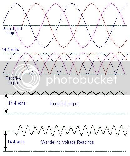
StatorOutput-1.jpg

The top drawing is of the three phase output of the stator. Each phase is in a different color and is depicted that way in the other diagrams. The output of the stator is pure AC.

The second drawing shows what the stator output would look like after the rectifiers but without the battery connected. The battery is the equivalent of a big MF capacitor that filters out the ripple. All the power pulses from the stator are now positive going from ground.

The third drawing shows the residual ripple that the battery is unable to filter out. The ripple is what causes the last digit of the volt meters to flicker. It can also be responsible for buzz in audio and communications gear.

The fourth drawing is representative of the 'wandering reading'. The battery has both the residual ripple and an additional oscillation. Circuit resistance, battery condition and load stability contribute to the amount of ripple and oscillations. Headlight = stable load. Audio equipment = unstable load, the electrical load varies with sound volume.
 
Last edited by a moderator:
I've said it before, and I'll say it again... despite all the off-topic stuff and whatnot, I learn more useful stuff about my motorcycle every day by following threads like this...

Thanks Guys! :clapping:

 
Looks like we have a pretty good argument for replacing the battery on a regular schedule rather than waiting for it to die. I know that some folks have reported using the same battery, on other bikes, for as long as seven years, but they probably didn't have the electronics for fuel injection and spark that we have on the FJR.

 
Looks like we have a pretty good argument for replacing the battery on a regular schedule rather than waiting for it to die. I know that some folks have reported using the same battery, on other bikes, for as long as seven years, but they probably didn't have the electronics for fuel injection and spark that we have on the FJR.
Agree. Why wait to get caught or stranded at an inopportune time or place that might cause pushing, an accident, or worse? So how long can we push the battery life before we have to push the bike? Is three years reasonable?

 
Last edited by a moderator:
10/2002 and counting

which means someone better bring a set of those light-weight jumper cables to the AR ride. Any time someone posts a response like this, it's just like painting a big target on their back.

a ditto to skooter's heat and having a replacement already on hand (below). i'm used to batteries lasting about 2.5 years on the wings, so this one has lasted much longer than i expected.

 
Last edited by a moderator:
Status
Not open for further replies.
Top