KrZy8 Gen2 - Charging Circuit

Yamaha FJR Motorcycle Forum

Help Support Yamaha FJR Motorcycle Forum:

This site may earn a commission from merchant affiliate links, including eBay, Amazon, and others.
Well, Roadstercycle is gone for vacation, so some of my money is safe for a week or two, but I do have a question or two (or three, or four);

1. Is the connector he sells waterproof (given where Yamaha has placed the RR)?

2. Does he sell the output connector separately or is he offering an 'output kit' only perhaps? If yes to either, then do you know for how much?

3. How much wire do we REALLY need when all is said and done?

4. Can we pull out the old wiring without slicing things up?

Thanks

Edit: Another question (or 4, or 5)

Circuit breakers tend to 'weaken' in terms of their trip current as they are operated. I'd be inclined to ensure that as few trips as possible are encountered. so;

5a. Is the circuit breaker auto-reset?

5b. Does he offer a larger one, given that you measured 28 amps draw?

5c. I don't recall seeing a pic of the breaker. Where did you put it?

6a. Do you know if he will offer a complete kit specific to the FJR Gen-II?

6b. Will Eastern Beaver get 10 (or 8) gauge wire and offer a complete, pre-built solution?
The way I ran the loom (see pics in earlier post and more detailed explanation) I used around 6ft of wire.

The connector Jack sells is the OEM one, so it's as waterproof as the one on your FJR now.

The max rating of the circuit breaker Jack sells is 30A which is plenty IMHO. My logic is that I'll not worry about it until I actually see it trip, which will be blatantly obvious since I have clear view of the Datel and the Escort at all times. Since this circuit breaker auto resets it will simply start working again very soon I imagine...

You can buy whatever bits of the kit you want, I just bought the connector, terminals, wire, circuit breaker and the lugs for the circuit breaker and the battery terminals.

Last time I spoke with Jim from EB he said he did NOT have 10AWG wire/terminals and was not planning on getting them. I actually suggested to Jack to think about making a plug-n-play kit. He was interested but said that he does not have access to an FJR to measure things up, so if one of the local CA FJR owners want to hook up with him to let him have a look and take some measurements I think a kit will soon be available.

The location where I placed the circuit breaker makes it easily accessible (just pull off the front seat, it's the little red rectangle) it already has two ring terminals, so in the worst case scenario you can simply screw the two terminals together with a small bolt & nut. You can also see it by itself in the picture of the kit.

 
Last edited by a moderator:
Well, Roadstercycle is gone for vacation, so some of my money is safe for a week or two, but I do have a question or two (or three, or four);

1. Is the connector he sells waterproof (given where Yamaha has placed the RR)?

2. Does he sell the output connector separately or is he offering an 'output kit' only perhaps? If yes to either, then do you know for how much?

3. How much wire do we REALLY need when all is said and done?

4. Can we pull out the old wiring without slicing things up?

Thanks

Edit: Another question (or 4, or 5)

Circuit breakers tend to 'weaken' in terms of their trip current as they are operated. I'd be inclined to ensure that as few trips as possible are encountered. so;

5a. Is the circuit breaker auto-reset?

Yes. The 'MaxiFuse' holder can accept a regular fuse, manual reset, or auto reset. The 50 amp version is available with auto reset, 30 amp manual - at least from what I've been able to tell so far given a 3 minute google search.

5b. Does he offer a larger one, given that you measured 28 amps draw?

He plans to - he orders them just like you or I would. The key is that the MaxiFuse holder (big mama fuseholder) can accept a full 50 amp fuse/CB

5c. I don't recall seeing a pic of the breaker. Where did you put it?

Mine will be about 6 - 7 inches from the battery, nestled under the cowling, on the outside edge of the battery.

6a. Do you know if he will offer a complete kit specific to the FJR Gen-II?

He plans to keep the dimensions on hand should more fjr peeps want this kit.

6b. Will Eastern Beaver get 10 (or 8) gauge wire and offer a complete, pre-built solution?

See JamesK response.
The way I ran the loom (see pics in earlier post and more detailed explanation) I used around 6ft of wire.

That's what I measured out too, using the Easter Beaver harness.

The connector Jack sells is the OEM one, so it's as waterproof as the one on your FJR now.

He sells connector kits too. Eastern Beaver has connector components, Jack may too.

The max rating of the circuit breaker Jack sells is 30A which is plenty IMHO. My logic is that I'll not worry about it until I actually see it trip, which will be blatantly obvious since I have clear view of the Datel and the Escort at all times. Since this circuit breaker auto resets it will simply start working again very soon I imagine...

Why not just replace it with a 50 CB? I found some for like 3 USD per..

You can buy whatever bits of the kit you want, I just bought the connector, terminals, wire, circuit breaker and the lugs for the circuit breaker and the battery terminals.

Last time I spoke with Jim from EB he said he did NOT have 10AWG wire/terminals and was not planning on getting them.

I actually suggested to Jack to think about making a plug-n-play kit. He was interested but said that he does not have access to an FJR to measure things up, so if one of the local CA FJR owners want to hook up with him to let him have a look and take some measurements I think a kit will soon be available.

Yep!

The location where I placed the circuit breaker makes it easily accessible (just pull off the front seat, it's the little red rectangle) it already has two ring terminals, so in the worst case scenario you can simply screw the two terminals together with a small bolt & nut. You can also see it by itself in the picture of the kit.
Well, JamesK and I don't agree on *everything*, :lol: I want the fuse closer to the battery in case I start a weld job someday... Either location is OK, the key thing is to have the circuit fused!

My Roadster harness should be here when I get back from the Clan Gathering. For now, I'm off to go ride on Wabs! :p

Wanted to add that Jack has a video on how to disassemble those freaking RR connectors...

 
Last edited by a moderator:
Why not just replace it with a 50 CB? I found some for like 3 USD per..
Why not in deed although I really don't see it being needed, but you're right there are plenty of choices. The $3 on on eBay looks a little cheaper quality than the 30A CB Jack sells, but at 3 bucks I'll give it a try. These kind CBs seem to be a commonly used part in the boating world based on the ad descriptions on eBay, well boats and Hardleys :blink:

!CFb5(Jw!Wk~%24(KGrHqIOKj4E0tlsWurHBNVENH6boQ~~_12.JPG


I bet I can get to my CB under the seat quicker than you can to yours in the fairing :rolleyes:

On of my considerations for the placement under the seat was that the space where I located mine is otherwise wasted, whereas there is very precious little space left anywhere around the battery area in the fairing, at least on my bike with all the other farkle wiring around and running through there.

 
So if the wire gets shorted between the battery and the fuse under seat it will be a big ash fuse-able link. Then you'll have to get into the fairing and replace more than a fuse. :unsure: Just saying.

 
So if the wire gets shorted between the battery and the fuse under seat it will be a big ash fuse-able link. Then you'll have to get into the fairing and replace more than a fuse. :unsure: Just saying.
Ok, so would putting a similar CB on the -ve wire too be a worthwhile endeavor? I covered my wiring with a protective sheathing all the way along the run, with only about 2" of wire being not sheathed at the battery end and about 1" at the R/R end. Worth noting that the OEM setup seems to be far less protected than mine.

 
If you are seriously concerned, you should fuse the cable at BOTH ends, since both devices can source big current.

Note that if the cable opens and the RR runs unloaded it could well overheat and fry because it is a load shunting regulator, rather than a series regulator - series regulators get hotter with additional load. hunt regulators dump the excess power as heat and 50 or so amps at 14 volts will heat the regulator quickly while the bike is running on the batery.

The wiring diagram shows no fuse between the regulator and the battery . . . I wonder whether it doesn't make sense to do the same thing with any replacement harness?
Frank, actually I'm perfectly satisfied with the current level of "protection", I was just replying to roadruner's questions.

Regarding the functionality of the R/R, from what I've read about them, the FH012/020 actually work in a much more intelligent manner than the typical inferior R/R, these actually go open circuit vs. wasting power/resources by shunting it.

 
The new MOSFET RR will protect itself by shutting down, how it does it I don't know.Regarding current shunting, note that the scr's simply reroute, shunt, back to stator; no dc output is shunted to ground. You can actually take all 3 stator wires, connect, un bike, no damage, is what happens, essentially, when scr's fire. At least that's my understanding of 2tech papers I've read.

I'm on iPad, hard to type, more later.

 
...

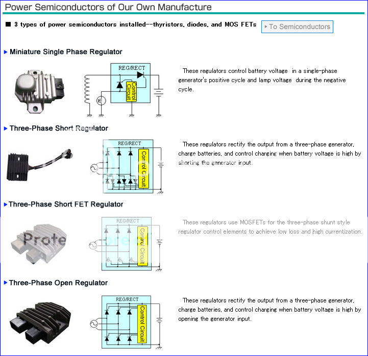
the FJR uses the "Three-Phase Open Regulator"

...
Somewhere in the back of my mind I seem to recall reading that the Gen1 uses the "Short" type, the Gen 2 the "Open".

But I could be wrong. Memory's getting worser, have to make allowances.
cryingsmiley.gif


I know that all the Gen I use a shorting regulator and the Gen II used a different regulator. Right now Yamaha specifies the same MOSFET regulator for all Gen II years. I'm not certain, but I believe that there was a change to the new style R/R sometime between the '06 and '10 models. The current Gen II R/R is backwards compatible from the '12 to the '06.

 
Many thanks to you Don and James.


I have been having this same problem for a few years and it got worse each year. Mine was at the point where it was running 13.6 on the road, but would drop to 12.9 if the fans came on. Increasing RPM's with the fans on would not help much. Heated gear was out of the question.


Following loosely in your footsteps I ran 8 ga. wire out of the RR. I used automotive female splices in the original connector but they had to be massaged considerably so they would lock in and line up correctly. The original wire water seals did not fit with the big wire so I packed the back of the plug with 3 little o rings on each wire to seal. I ran the new ground wire to the bolt holding the fwd bottom end of the rear subframe where I also attached the end of the original ground wire that used to go to the RR. The new positive wire was triple insulated full length without load protection to the positive side of the battery. The outer sheath is something we use on aircraft. I don't know what it is but you cannot cut it with a knife. Probably kevlar, not sure.


I started the bike and the voltage, which I had never seen more than 13.8, even when new, popped right up to 14.1 instantly, and when I blipped the throttle to 2500 RPM's it went to 14.25 and I shut it down as a little bit of pee ran down my leg. I was so exited I didn't even get mad when I had to take the gas tank skirt off again when I remembered I didn't connect the overflow hose.


Once the bike was all together and I started to clean up, I still didn't get upset when I noticed:


IMG_1744.jpg


Again, Thanks for sharing all your hard work.

 
Spectacular! I think the 'fix' will be confirmed multiple times by various peeps. Good on yah for getting 8 gauge wire in the connector.. Any pix?

 
Spectacular! I think the 'fix' will be confirmed multiple times by various peeps. Good on yah for getting 8 gauge wire in the connector.. Any pix?
Finally stopped raining so I got it out and ran till the fans came on. At first start it was 14.2 at high idle, then settled down to 14.0 at idle. When the fans came on it was 13.6 at idle,(1100 RPMS) and 13.9 at 2500 RPMS, . Before the fix it was 12.9 at idle with the fans and no improvement with higher RPMs.

No pics of the connector, sorry. But I used 10 gauge automotive connectors and the 8 ga. went in, just barely and with force. I soldered them. I had to cut a little window in them for the plastic lock tab and then they were crooked so the plastic plug body needed to be filed some and the mouth of the female connector had to be opened a little at the end so the bayonet would engage. Even at that it was a firm push to get them seated. Which is actually a good thing because the factory connectors were a very light fit on the bayonet. Certainly not worthy of that kind of power in my opinion which you actually proved by the voltage increase you got using the automotive connectors.

My bike slowly deteriorated over six years. I suspect that most Gen II's have this problem, it just hasn't gotten bad enough yet. Funny thing is, you can run all the ohmage (is that a word?) and voltage tests like you and I did, and they all show good. You need to have a load to see the deterioration.

I love this bike, but let's be honest, the wiring on the Gen II's is a nightmare.

 
This is all good to know. Like I said earlier, my bike has also been suffering in the voltage area. So I too will have to do this.

Thanks for sharing.

 
1344217933[/url]' post='988639']This is all good to know. Like I said earlier, my bike has also been suffering in the voltage area. So I too will have to do this.

Thanks for sharing.
By the time I get home the RC harness should be there, will install and hopefully confirm JamesZk results.

Oh, and Thanks for saying Thanks!
yahoo.gif


What is the RC harness ?

I was planning on running 10ga wire from RR to battery and put a breaker (30 or 50 amp)close to battery.

 
Last edited by a moderator:
See earlier posts for full details, Roadstercycle.com, Jack, is interested in making fjr specific harness. Should have proto by time I get home. Sorry for short post iPad kboard sux.

 
Top