KrZy8 Gen2 - Charging Circuit

Yamaha FJR Motorcycle Forum

Help Support Yamaha FJR Motorcycle Forum:

This site may earn a commission from merchant affiliate links, including eBay, Amazon, and others.
Yeah, I plan on replacing the wire, but the tech in me still wants to find the smoking gun. From what you all have done I'm sure it's the wire, but I want to run a test before I replace it. I just don't have time to get into it now.
I agree. It would be very valuable to know where this added resistance is coming from. Seeing as it is a slowly developing, chronic problem, it may be an accumulation of multiple small resistances in each of the connection points. Every crimp and connector is suspect. But it is also possible that the wire itself that Yamaha used is not aging gracefully and the resistance of the wire is actually increasing with time and weather.

I think the wire needs to be tested under a load. An ohm meter is no good. Even a tiny wire has continuity. I think there is a tester called a Megger. It not only tests continuity but also load capacity? I'm not sure. Where is Alan?
No, a megger is used to measure very high resistances (megohms) like in insulation leakage tests. In this circumstance we are looking for very low resistances. The instrument that you use to make low resistance measurements is a 4 wire Kelvin meter, and not many folks will have one of those laying around. (ionbeam may, I don't)

The bike itself is a pretty good low resistance, high load tester. All you need do is determine the current going through the wire and then measure the voltage drop across each component to know the resistance of it. The current is the same everywhere along the entire series circuit, so you just need to measure that (under the desired load) once and then use a digital DC voltmeter to make measurements across the component in question. Voltage / Current = Resistance

If you want to do the same thing out of circuit, just hook up an external DC power supply (battery) with some current limiting resistance added, measure the current and then the voltage drop on the component under test. A voltmeter is much more accurate than an ohm meter at these low resistance values (an ohm or less).

One thing to keep in mind is that copper, like most metals, has a positive temperature resistivity coefficient. It gets more resistive as you heat it. And as you run current through it, you heat the wire. So, some of this mysterious resistance may be a bit of thermal effect in the wire harness. In other words, it may measure fine when it is hooked up to a low current source or tester, but have much higher resistance when you are hitting it with 30 amps.

Of course this brings up my earlier pondering a few posts back - does the inferior R/R wiring, connectors, etc. lead to the early demise of the R/R and/or Stator because both of these components end up having to work at max capacity ALL the time just to try to provide sufficient Voltage to charge the bike.
This should not be the case. An increased resistance of the output wiring will actually limit the amount of current out of the R/R. The generator and regulator will not be "working" any harder. What causes the Stator to overheat is when you ask it to supply more current than it is capable of. The windings of the stator heat up, become increasingly more resistive, which causes more heat, etc.

So having too many high power consuming devices is how you burn out stators. Don't forget that a bad battery can be a very high power consuming device, if it requires constant charging.

 
Last edited by a moderator:
Yes, lots of people have had BDS, to the point where the bike doesn't have enough juice in it to start the bike. Which is the whole point of having a panel Battery Volt meter in the dash. But generally BDS only happens if they are running too many high power consuming accessories, such as aux lights and heated gear. Little stuff like GPSes, intercoms, etc you'll never have a problem.

PS - It's not an analogy. It actually is one. Albeit a chemical storage of voltage vs electrostatic.
Strictly speaking, the battery is a capacitor but i tend to think of a capacitor as an electrostatic device rather than a chemical device. Perhaps accumulator is a better term? I digress...

Anyway, once I get the aux lights and start using the heated gear (hopefully not too soon!), I will carry a DVM around for long enough to assure myself that I don't have a problem. The auxilliary lights I bought are HID (35 W each after startup) so as long as the charging system is OK, I should have lots of capacity.

I'll bookmark this thread in case I run into problems.

Ross
Yabbut, that will only tell you everything is OK right then. Things change.

Most people learn to use the panel voltmeter so they can turn on and off various loads at various times. IOW, once you start dabbling with heated gear you probably won't be able to run everything that you have installed on your bike all at the same time without riding battery discharge.

PS - FYI... 35W HID lights use much more than 35W a piece after startup due to losses in the ballast circuits. Closer to 45W each. Measure yours to know for sure.

Why not just install a panel voltmeter? They aren't that expensive and are pretty easy to install.

 
I think the wire needs to be tested under a load. An ohm meter is no good. Even a tiny wire has continuity. I think there is a tester called a Megger. It not only tests continuity but also load capacity? I'm not sure. Where is Alan?
The piece of information you need is the 'volts drop' along the positive wire from the RR to the battery.

Suggest you connect a (Digital Volt Meter) DVM, set on DC Volts with the positive lead connected at the RR positive & the negative lead connected at the battery.

Start the engine and apply loads in stages and record the volts drop each time. If you can actually measure current through that wire at the same time that would be ideal.

It's probably worth repeating this for the negative wire from the RR to the battery.

As far as I am aware a 'Megger' is an insulation tester, no practical use in this application.

Hope that helps

Don
Don

That is just what I want to check. I want to see how much of the charge current goes threw the gage. I'll do the test with bike running, grips on high, heated coat on high, etc. If all the wiring is good then ideally 0.0-0.2 volts will go threw gage, but we know that's not the case so I want to see how much can't go threw the stock wiring and has to go threw the test gage. Then I would like to check each section and connector along the pos wire to try to find the exact spot of the drop. I may see there's a little in every section and connector, if so then I'll replace the entire pos wiring.

 
Does this mean you may put a kit together for us clueless electron challenged people? As I said on my 2010 they (the shop) are looking for 14.0. Mine is 13.90 and was mentioned to me only in passing after the service. However the comment was with all the things you have on there it is not an issue and nothing to worry about.

I do.
I don't plan on it at this time. DC posted a place you can get a kit.

Here it is link

 
Last edited by a moderator:
Don

That is just what I want to check. I want to see how much of the charge current goes threw the gage. I'll do the test with bike running, grips on high, heated coat on high, etc. If all the wiring is good then ideally 0.0-0.2 volts will go threw gage, but we know that's not the case so I want to see how much can't go threw the stock wiring and has to go threw the test gage. Then I would like to check each section and connector along the pos wire to try to find the exact spot of the drop. I may see there's a little in every section and connector, if so then I'll replace the entire pos wiring.
That's not exactly how the test works. The current that goes through the voltmeter is very small. In fact, the ideal voltmeter draws no current from the circuit under test at all. When you are measuring the voltage drop across the wire (for all intents and purposes) all of the current still goes through the harness wire. You'll just be determining how much voltage is being dropped across it.

As you increase the current through the harness (by turning on more accessories) that voltage drop will absolutely increase. It has no choice to do otherwise. What you want to know is, is the resistance also increasing? You can only determine that by knowing the current going through the harness at each measurement.

edit - Donal posted while I was typing

 
Last edited by a moderator:
...Where is Alan?
In Pittsfield, MA beating quality into a plastic injection molding company. However, Fred has made me unnecessary by supplying the whole, correct answers.

...The instrument that you use to make low resistance measurements is a 4 wire Kelvin meter, and not many folks will have one of those laying around. (ionbeam may, I don't)
I have access to a Kelvin Probe meter but given the power that we are talking about in a motorcycle it isn't the best tool for the job.

The bike itself is a pretty good low resistance, high load tester...And as you run current through it, you heat the wire...
DING! DING! That is for true. The 'meter' you need is readily at hand. Resistance = voltage drop = heat. Use your highly calibrated finger and touch the various locations where voltage drop is suspected. If there is enough current draw (or resistance) to cause a voltage drop, that location will be warm to hot. Temperature will be proportional to voltage drop. If it is a little warm, there is a little voltage drop. If you blister your finger there is a huge voltage drop. I'm sure that the main fuse will be warm under moderate current draw.

-- A resettable DC circuit breaker like these would be a great substitute for the main fuse to eliminate that as a current drop item. --


Don

That is just what I want to check. I want to see how much of the charge current goes threw the gage. I'll do the test with bike running, grips on high, heated coat on high, etc. If all the wiring is good then ideally 0.0-0.2 volts will go threw gage, but we know that's not the case so I want to see how much can't go threw the stock wiring and has to go threw the test gage. Then I would like to check each section and connector along the pos wire to try to find the exact spot of the drop. I may see there's a little in every section and connector, if so then I'll replace the entire pos wiring.
That's not exactly how the test works. The current that goes through the voltmeter is very small. In fact, the ideal voltmeter draws no current from the circuit under test at all. When you are measuring the voltage drop across the wire (for all intents and purposes) all of the current still goes through the harness wire. You'll just be determining how much voltage is being dropped across it.

As you increase the current through the harness (by turning on more accessories) that voltage drop will absolutely increase. It has no choice to do otherwise. What you want to know is, is the resistance also increasing? You can only determine that by knowing the current going through the harness at each measurement.

edit - Donal posted while I was typing
So is my test no good ? I thought it was an easy way of checking the circuit to see if it could handle the loads. Isn't it just another way of checking the same thing ? you know tomato, tomoto.

So if I was to run a 4ga wire from RR to battery I would still see higher drop under load ? :huh:

Now I'm confused.

 
I may be missing something here. Modern Digital Multimeters set to the voltage scale have input resistance of ≥ 20 meg ohms. When probing a 14 volt circuit the meter would be drawing 7 nano amps.


I'm not sure where the confusion is coming from about the voltage drop test. Voltage drop will become less and less at the wire becomes fatter. Saying the wire gauge gets larger -- 30 ga is very thin, 10 ga is substantial, 1 ga is very big. So, wire diameter gets bigger as the numbers get smaller.

 
Were I'm confused is as loads increase so does volt drop. I thought if the wiring was capable of handling it , there would not be an increase in volt drop.

edit; I think the more current you pass threw a wire the more will drop, but it should still be in the exceptable range of say 0.0-0.5 volts if the wiring is OK. If I see more than 0.5 volt drop then something is bad. Is this not correct ?

 
Last edited by a moderator:
Alright, let me see if I can clarify this some:

Any piece of wire has a particular amount of resistance at nominal room temperature. The resistance of wires varies proportionally with the diameter of the wire, length of the wire, and (to some extent) the temperature of the wire. When you run current though it there will always be a voltage drop across that resistance. This resistance is usually quite small, and currents are usually relatively small, so the amount of voltage drop on the wire is negligible. In this case the current is quite large, so even with a relatively small amount of resistance the voltage drop can become substantial.

The formula for calculating voltage drop is Current * Resistance = Voltage (this is known as Ohm's Law).

So as an example, a particular wire that has just 0.1 ohms of resistance (which is the threshold of what you can measure with a Digital Ohm meter) when you run 1 amp of current through it, would drop 0.1 volt across that resistance. Now take that same wire and run 30 Amps of current through it and you will then drop 3.0 volts across that same 0.1 ohm resistance.

So knowing all of this we can calculate how much that very small wire resistance actually is (since we can't measure it with an ohm meter) just by twisting that calculation around. If we measure the voltage drop on the wire and we know the current that's going through it we can calculate the resistance of it.

If you go to a larger gauge (lower AWG number) wire that has a lower resistance, lets say it is now just 0.01 ohms of resistance. With the initial 1.0 amp of current there will still be a voltage drop on the wire, but it will only be 0.01 * 1 = 0.01 volts. And when you run the current through the wire up to 30 amps the voltage drop will still go up, just now it will be .01 * 30 = only 0.3 Volts.

Is this making better sense?

 
Last edited by a moderator:
Yes it all makes sense, but hard to wrap my head around it all.

I like to keep it simple, for me a voltage drop test is simple. If I see more than 0.5 volt drop isn't that a good way of seeing sumpin isn't good. :dntknw:

 
Yes it all makes sense, but hard to wrap my head around it all.

I like to keep it simple, for me a voltage drop test is simple. If I see more than 0.5 volt drop isn't that a good way of seeing sumpin isn't good. :dntknw:
Simple ansewer is yes :blink: but (there's always a but) Alan's suggestion is the simplest way to narrow it down after you complete the initial voltage drop test.

As Alan & Fred have already said, the voltage drop you measure is just an indication of volts (think pressure) lost along the wire. There's no need to think of anything bypassing through the DVM.

Don

 
EZ Ohms Law:

OhmsLawjpg.jpg


In electronics:

E = Voltage

I = Current

R = Resistance

Here is how it works --

To solve for Voltage (E), see the blue box with the E? Put your thumb over the E, that leave the two boxes below. That means you are supposed take the remaining I and R and multiply them together to solve for Voltage.

To solve for Current ( I ) cover the pink I, that leaves E and R. Divide E by R, the answer will be circuit current.

To solve for Resistance ( R ) cover the green box, that leaves E and I. Divide E (voltage) by I (current) and you get resistance.

Watts = Voltage x Current Example: 14 volts x 30 amps = 420 watts Other example 14 volts x 3 amps = 42 watts which is what your typical heated grips draw.

We know voltage and current, so to solve for resistance cover the green R and divide E (voltage) by I (current) and you get 4.6 ohms. The grip heating elements can not total more than 4.6 ohms or they will not be able to produce 42 watts of heat. Since there are two grips, each grip has to be 2.3 ohms.

14 volts / 40 amps = 0.35 ohms The resistance of the wiring can not be MORE than 0.35 ohms or 40 amps can not flow. The wire must be less than 0.35 ohms or the voltage will drop. 14 volts / 0.44 ohms = 31 amps. The difference between 0.35 ohms and 0.44 ohms in the wiring will cause the current flow to be reduced by 9 amps.

 
Last edited by a moderator:
After catching up on the recent posts I now need to go and take 2 Aspirin.

But the good news is I took the bike to work today. I saw a momentary 14.35V on fast idle when cold and during the slowish 45 min ride to work it hovered between 14.15V and 14.25V with RPM's between 2500 and 3K.

This new found power is awesome. I am now looking at plans to install air conditioning and a small fridge.

 
OK Guys. thanks for the edjumakation. skools over.

When I get around to checking it I'll refer to this.

Thanks

I gotta get this fixed cause I also want an air conditioner.

 
Does this look right to you? The offset terminals in this maxiFuse holder?

Had to bend the fuse leads to make it fit?

136.jpg


This whole thread has me all fuked up... I can't put the battery's in a vibrating butt plug right. :dribble:

 
Last edited by a moderator:
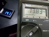
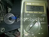
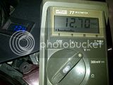
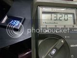
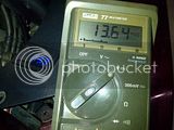
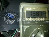
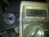
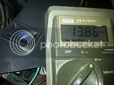
Based on S76's logic I decided there was no harm in independently grounding the -ve wire from the OEM R/R plug. While I was at it I figured I'd take just one more set of readings, comparing the Volts I could see on the bypass R/R loom vs. the +ve wire on the OEM R/R plug. My original thought was that since this OEM wiring is now NOT carrying (or shouldn't be anyway) a lot of load there should be minimal differences b/w the readings. As you can see from the pics below my hypothesis wasn't worth squat :unsure: but it did prove if I understand the results correctly that the OEM wiring is crap, and that there are loads hanging off of it (maybe some of the smarter folks could confirm/deny based on the scenario & pics below?

Here is the test setup:

- My Datel is wired directly across the Battery, only running to a tiny (solid-state) relay hooked up to ACC.

- The Fluke77 was hooked up as follows:

......-ve probe on the Batt -ve (also tried on the chassis but could not distinguish any differences in readings).

......+ve probe was plugged into the OEM R/R plug +ve terminal.

I also took some similar measurements with the OEM R/R plug -ve terminal independently grounded to the chassis but again could not distinguish any differences in readings. At most possibly in the 0.02-0.03V which is only observable on the Fluke since my Datel only goes to the first decimal place (XX.X Volts).

These readings are at idle with just the "standard" loads, HID headlights, some led marker lights, RD, Fans Off.


These readings show the Voltage change as the Fans first kick in and for the next minute or more to observe the charging system recovering and settling to a stable/nominal output under the given load (Fans On plus all the "standard" loads).


It is interesting to me how the readings on the OEM R/R +ve terminal and the Datel (connected directly across the Battery) practically converge just as the Fans first kick in, but quickly start to diverge as the charging system begins to recover as you can see from the above pics.

Charging system recovered and running stable with the Fans On, bike at around 1,100 rpm idle.


Fans cycle Off


After catching up on the recent posts I now need to go and take 2 Aspirin.

But the good news is I took the bike to work today. I saw a momentary 14.35V on fast idle when cold and during the slowish 45 min ride to work it hovered between 14.15V and 14.25V with RPM's between 2500 and 3K.

This new found power is awesome. I am now looking at plans to install air conditioning and a small fridge.
Bob, I've got Voltage envy :dribble: all my FJR can manage is 14.1V on the Datel

But I do have some extra loads that are always on, iPhone charger, 2xLED marker lights, AddMore lights in the Givi topbox, audio amp, Scorpio Alarm, Laser Jammer, RD, 2xGPS, Cruise Control which are always on so hopefully all these combine to "use up" the 100-150 mV that you are seeing but I'm not. Honestly I don't believe the difference is due to your 8AWG vs. my 10AWG wiring used for the R/R bypass. But potentially some minor portion might be due to the fact that you used better fitting connectors than the OEM type Furukawa plug and terminals?

 
Top