KrZy8 Gen2 - Charging Circuit

Yamaha FJR Motorcycle Forum

Help Support Yamaha FJR Motorcycle Forum:

This site may earn a commission from merchant affiliate links, including eBay, Amazon, and others.
Completely off the subject, Don, but your Feej sounds like ass.

You got some kind of squidly aftermarket-crap exhaust on KrZy8?

Never once sounded like she was runnin' smooth, and bitched/popped like hell on decel, too.

 
OK, wading thru your data, it looks like the 6 ohms between the RR and battery is pretty significant to me. If you find those 6 ohms you'll find your lost voltage.

The reason the voltage difference is low when nothing is running is you aren't drawing any current through that resistance. As soon as you start the bike and add a load you start to draw current which results in a voltage drop across the resistance. You should be able to find that resistance with the ohm meter, and the bike not running.

 
Last edited by a moderator:
OK, wading thru your data, it looks like the 6 ohms between the RR and battery is pretty significant to me. If you find those 6 ohms you'll find your lost voltage.

The reason the voltage difference is low when nothing is running is you aren't drawing any current through that resistance. As soon as you start the bike and add a load you start to draw current which results in a voltage drop across the resistance. You should be able to find that resistance with the ohm meter, and the bike not running.
Fred, the resistance 0.6 to 0.9, less than 1 ohm. Is that acceptable?

..and yes on current through resistance = voltage drop across resistance.

 
Out of my league, but I'm looking at a Gen I wiring diagram and see a pretty direct path for the positive power circuit from the R/R through the main fuse to the battery. There isn't much opportunity for resistance in that path unless the wire is too small, corroded, damaged or the fuse connections are poor. Resistance usually = heat and may be visible. This bike has had a kind of weird history, so I wouldn't take the wiring integrity as an assumption. Just curious does the Gen II use a 50 amp main fuse?

It would not be hard to splice into that circuit near the R/R and run a 10 GA bypass through an inline 50 amp fuse to the battery and see if this problem disappears.

 
Last edited by a moderator:
OK, wading thru your data, it looks like the 6 ohms between the RR and battery is pretty significant to me. If you find those 6 ohms you'll find your lost voltage.

The reason the voltage difference is low when nothing is running is you aren't drawing any current through that resistance. As soon as you start the bike and add a load you start to draw current which results in a voltage drop across the resistance. You should be able to find that resistance with the ohm meter, and the bike not running.
Fred, the resistance 0.6 to 0.9, less than 1 ohm. Is that acceptable?

..and yes on current through resistance = voltage drop across resistance.

Sorry I missed the decimal in my post. Yeah, 0.6 ohms (lead corrected) seems excessive to me for a short stretch of wire.

 
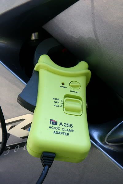
I am hesitant to correct Dr. Ionbeam, but I think you really want the TPI A256 rather than the A250. If I read the spec's right, the A250 is only good for AC while the A256 goes both ways. :eek:
In another related thread I posted a picture of my amp probe which is indeed a TPI A256 and not the A250. Here is the picture of my amp probe --

IMG_8551sm.jpg


OK, wading thru your data, it looks like the 6 ohms between the RR and battery is pretty significant to me. If you find those 6 ohms you'll find your lost voltage.

The reason the voltage difference is low when nothing is running is you aren't drawing any current through that resistance. As soon as you start the bike and add a load you start to draw current which results in a voltage drop across the resistance. You should be able to find that resistance with the ohm meter, and the bike not running.
Ideally, to get an accurate resistance reading there should be no voltage on the wire (the battery should be disconnected). Also, it is difficult for someone that isn't an electrical type to make accurate resistance measurements below 20 Ω because of lead resistance and the necessity of good contact. When people tell me they ohmed their stator and it measured 0.2 Ω per the FSM I get a little worried. Take any standard DMM, set it to the lowest ohm scale and touch the leads together, the meter will typically read the lead resistance of 0.2 to 0.6 ohms which is greater than the value they are trying to measure.

Off line I sent Dcarver a structured list of tests to perform which included a voltage drop test from the R/R to the battery going through each item in the path of the positive and negative side. We are trying to track down less than one missing volt, which isn't much.

Sorry I missed the decimal in my post. Yeah, 0.6 ohms (lead corrected) seems excessive to me for a short stretch of wire.
Yes, 0.6 ohms is a LOT for a 50 amp circuit. Refer back to my saying that measuring low resistance can be tricky. Also, the 50 amp main fuse is in fact a small resistor which will have a voltage drop similar to a shunt resistor. Only this resistor is made so that its resistance will cause it to heat in a way that at 51 amps it gets so hot it melts.

 
Last edited by a moderator:
I am hesitant to correct Dr. Ionbeam, but I think you really want the TPI A256 rather than the A250. If I read the spec's right, the A250 is only good for AC while the A256 goes both ways. :eek:
In another related thread I posted a picture of my amp probe which is indeed a TPI A256 and not the A250. Here is the picture of my amp probe --

IMG_8551sm.jpg


OK, wading thru your data, it looks like the 6 ohms between the RR and battery is pretty significant to me. If you find those 6 ohms you'll find your lost voltage.

The reason the voltage difference is low when nothing is running is you aren't drawing any current through that resistance. As soon as you start the bike and add a load you start to draw current which results in a voltage drop across the resistance. You should be able to find that resistance with the ohm meter, and the bike not running.
Ideally, to get an accurate resistance reading there should be no voltage on the wire (the battery should be disconnected). Also, it is difficult for someone that isn't an electrical type to make accurate resistance measurements below 20 Ω because of lead resistance and the necessity of good contact. When people tell me they ohmed their stator and it measured 0.2 Ω per the FSM I get a little worried. Take any standard DMM, set it to the lowest ohm scale and touch the leads together, the meter will typically read the lead resistance of 0.2 to 0.6 ohms which is greater than the value they are trying to measure.

Off line I sent Dcarver a structured list of tests to perform which included a voltage drop test from the R/R to the battery going through each item in the path of the positive and negative side. We are trying to track down less than one missing volt, which isn't much.
Yup, fully understood. And that offline info (after he copied me in on your PMs ;) ) is what led me to believe the resistance is real and probably important. He be dropping milli-volts all over the place.

For anyone (trying to) follow along, this is not a life or death crisis here by any means. Nothing to get your panties too tightly twisted about. DC, being an anal retentive type A guy like me (yet he does have a soft creative side to him :rolleyes: ) is worried that his battery charging system is not "quite up to snuff." He is not in danger of being stuck on the side of the road like some poor BMW riding slob with a flaming final drive. :eek: But when people are fully in-tune with their bikes they know that, in general, a difference noticed is not a good thing in the long term.

In search of missing millivolts continues...

 
Last edited by a moderator:
Fred, note that while you were posting I was adding on to the end of the previous post.

For those on the sidelines that didn't see my troubleshooting guide for Don, it ends like this:

If you can't find the missing volts by now you need to leave your FJR on a busy street with the keys in the ignition :lol: (Or, stress less because you have proven everything is working correctly and just go ride it.)
 
Ideally, to get an accurate resistance reading there should be no voltage on the wire (the battery should be disconnected). Also, it is difficult for someone that isn't an electrical type to make accurate resistance measurements below 20 Ω because of lead resistance and the necessity of good contact. When people tell me they ohmed their stator and it measured 0.2 Ω per the FSM I get a little worried. Take any standard DMM, set it to the lowest ohm scale and touch the leads together, the meter will typically read the lead resistance of 0.2 to 0.6 ohms which is greater than the value they are trying to measure.Off line I sent Dcarver a structured list of tests to perform which included a voltage drop test from the R/R to the battery going through each item in the path of the positive and negative side. We are trying to track down less than one missing volt, which isn't much.

Yes, 0.6 ohms is a LOT for a 50 amp circuit. Refer back to my saying that measuring low resistance can be tricky. Also, the 50 amp main fuse is in fact a small resistor which will have a voltage drop similar to a shunt resistor. Only this resistor is made so that its resistance will cause it to heat in a way that at 51 amps it gets so hot it melts.
The resistance measurement was taken with battery disconnected and DVM leads zeroed out. I even checked the zero after running the test. :lol: I'll do it again tonight when I get home, just to be sure; I'm 85% confident the .6 to .9 number is correct.

I am hesitant to correct Dr. Ionbeam, but I think you really want the TPI A256 rather than the A250. If I read the spec's right, the A250 is only good for AC while the A256 goes both ways. :eek:
In another related thread I posted a picture of my amp probe which is indeed a TPI A256 and not the A250. Here is the picture of my amp probe --
IMG_8551sm.jpg
OK, wading thru your data, it looks like the 6 ohms between the RR and battery is pretty significant to me. If you find those 6 ohms you'll find your lost voltage.The reason the voltage difference is low when nothing is running is you aren't drawing any current through that resistance. As soon as you start the bike and add a load you start to draw current which results in a voltage drop across the resistance. You should be able to find that resistance with the ohm meter, and the bike not running.
Ideally, to get an accurate resistance reading there should be no voltage on the wire (the battery should be disconnected). Also, it is difficult for someone that isn't an electrical type to make accurate resistance measurements below 20 Ω because of lead resistance and the necessity of good contact. When people tell me they ohmed their stator and it measured 0.2 Ω per the FSM I get a little worried. Take any standard DMM, set it to the lowest ohm scale and touch the leads together, the meter will typically read the lead resistance of 0.2 to 0.6 ohms which is greater than the value they are trying to measure.Off line I sent Dcarver a structured list of tests to perform which included a voltage drop test from the R/R to the battery going through each item in the path of the positive and negative side. We are trying to track down less than one missing volt, which isn't much.
Yup, fully understood. And that offline info (after he copied me in on your PMs ;) ) is what led me to believe the resistance is real and probably important. He be dropping milli-volts all over the place.For anyone (trying to) follow along, this is not a life or death crisis here by any means. Nothing to get your panties too tightly twisted about. DC, being an anal retentive type A guy like me (yet he does have a soft creative side to him :rolleyes: ) is worried that his battery charging system is not "quite up to snuff." He is not in danger of being stuck on the side of the road like some poor BMW riding slob with a flaming final drive. :eek: But when people are fully in-tune with their bikes they know that, in general, a difference noticed is not a good thing in the long term.In search of missing millivolts continues...

Fred, note that while you were posting I was adding on to the end of the previous post.For those on the sidelines that didn't see my troubleshooting guide for Don, it ends like this:

If you can't find the missing volts by now you need to leave your FJR on a busy street with the keys in the ignition :lol: (Or, stress less because you have proven everything is working correctly and just go ride it.)
Well,actually, I think it's more of a problem than you think? I can't run HID lights or even just a heated jacket without dropping down below 12 vdc as measured across battery terminals using a Fluke 87.

No LoadIdle VDC = 13.2

5000 rpm = 13.5 vdc

HID Lights On

Idle VDC = 11.8

5000 rpm = 12.3

But what about his ****** sounding exhaust in the videos????Let's talk about something IMPORTANT FOR A CHANGE!!!
LOL, I'll be happy to tell you the secret behind that GREAT exhaust sound.


.

.

.

Remove your mufflers! :p

On a serious note, mucho gracias, Thank You, to Alan, Fred, and Mike for helping me diagnose this problem!

 
Last edited by a moderator:
Fred, note that while you were posting I was adding on to the end of the previous post.

For those on the sidelines that didn't see my troubleshooting guide for Don, it ends like this:

If you can't find the missing volts by now you need to leave your FJR on a busy street with the keys in the ignition :lol: (Or, stress less because you have proven everything is working correctly and just go ride it.)
Ionbeam, my FJR has been afflicted with the DCCD (Don Carver Charging Disorder :rolleyes: ) for as long as I can remember, well at least I never see 14.1-14.5 type readings on the Datel (hooked up directly across the battery) that many others are reporting/take for granted. So I was wondering if you would mind sharing that "off-line" list of additional tests?
Great idea James! If Alan says OK, I'd actually like to put together a charging circuit tip page for others who suffer charging woes. In the meantime, I have compiled many of the 'fart smellers' ideas here.. :lol:
 
Out of my league, but I'm looking at a Gen I wiring diagram and see a pretty direct path for the positive power circuit from the R/R through the main fuse to the battery. There isn't much opportunity for resistance in that path unless the wire is too small, corroded, damaged or the fuse connections are poor. Resistance usually = heat and may be visible. This bike has had a kind of weird history, so I wouldn't take the wiring integrity as an assumption. Just curious does the Gen II use a 50 amp main fuse?

It would not be hard to splice into that circuit near the R/R and run a 10 GA bypass through an inline 50 amp fuse to the battery and see if this problem disappears.
I was just thinking the same thing! :lol:

Fred, note that while you were posting I was adding on to the end of the previous post.

For those on the sidelines that didn't see my troubleshooting guide for Don, it ends like this:

If you can't find the missing volts by now you need to leave your FJR on a busy street with the keys in the ignition :lol: (Or, stress less because you have proven everything is working correctly and just go ride it.)
Ionbeam, my FJR has been afflicted with the DCCD (Don Carver Charging Disorder :rolleyes: ) for as long as I can remember, well at least I never see 14.1-14.5 type readings on the Datel (hooked up directly across the battery) that many others are reporting/take for granted. So I was wondering if you would mind sharing that "off-line" list of additional tests?
Great idea James! If Alan says OK, I'd actually like to put together a charging circuit tip page for others who suffer charging woes. In the meantime, I have compiled many of the 'fart smellers' ideas here.. :lol:
James, found a real nice troubleshooting flow chart here for pdf download or here to view it.
 
Some questions for the experts regarding some of the data above?

  1.  
  2. House load, no fuel pp, low beams = 3.2 amps - acceptable?
  3. Fuel pump is drawing 3.9 to 4.0 amps - acceptable?
  4. Stator unloaded VAC output has max deviation of 3 VAC - acceptable?
  5. Ground cable to various frame points max resistance .2 ohms - acceptable?
  6. Stator Vac INPUT, loaded A-B = 1.6, A-C = 1.8, B-C = 11.1 - normal, acceptable?


I read over here that

The regulator-part of the regulator-rectifier needs to measure the DC-voltage somewhere in the system. On the cheapest built units (quite a lot of OEM ones) this is done not by measuring the DC-voltage in the DC-system, but by looking at the AC-voltage in between one stator-phase and the ground, and sometimes the excess power is shorted to ground from just one or two input-AC phases instead of all three phases that are regulated. The better built units measure the output-voltage of the unit itself and regulate the input AC accordingly by shorting more or less power to ground, an equal amount off all three phases.
Does the FJR shed to ground via 1 or 2 AC phases or all 3? If so, could this explain why phase B-C at 11.1 vac is much higher than A-B or B-C?

 
Does the FJR shed to ground via 1 or 2 AC phases or all 3? If so, could this explain why phase B-C at 11.1 vac is much higher than A-B or B-C?
All 3-phases. The magic that goes on between the rectifier and regulator is kinda complex. An EE at a cruiser forum I was active at made a great effort to explain it in layman's terms. He partially succeeded and it's a good read, but still complicated. How a 3-Phase Stator and R/R work
Great find, Thanks, Tom. Already printed out... and saved to computer too.
 
Another Friday night spent troubleshooting. It's OK, KrZy8 is worth some hospital time.

I haven't found the root cause problem yet. Yes, I've expended energy, but no <positive> results.

Yes, I'm somewhat frustrated, but will prevail.

Tonight was 'find the bad connector night'.

Yeah, right.

Cleaned all 'power line' connectors I could find with CRC Electric Cleaner (swabbed with Q-Tip) then coated with Radio Shack cleaner/lubricant the with RS lubricant I could find. I now know more about how the main wiring harness on a FJR routes than I should, yet no <good> results.

I think I've located all mechanical connectors between the RR output and 'battery side', cleaned and lubed them all. No real improvement.

Will post up in a bit all steps taken tonight..

 
To figure out where your gremlin is, we may need to get another helpful 2nd gen owner to make those same measurements that you have made on a healthy bike, ideally with the same test equipment.

I'm also now suspect of the .7 ohm measurement. 7 amps (or more with engine running)) through a .7 ohm resistance would result in a 5 volt drop, not a few millivolts.


Latest posts

Top