• If you have bought, sold or gained information from our Classifieds, please donate to FJRForum and give back.

    You can become a Supporting Member or just click here to donate.

LEDRider LED Floods and Spots - FJR Forum discount

Yamaha FJR Motorcycle Forum

Help Support Yamaha FJR Motorcycle Forum:

This site may earn a commission from merchant affiliate links, including eBay, Amazon, and others.
Just got the dimmer prototypes today. I snapped a few quick pictures below. I am very happy with the design so far. The cases are 2 inches square, with a big glove friendly knob. Red/Black wires on the right are +/- 12v input. On the left, Red/Black is output to the lights, Blue is a trigger wire that bypasses dimming function when ~12v is applied (from stock highbeam wire etc). The knob has a full "off" position, so no switch is needed (i.e. totally off, bypass does not turn on lights). The lights are also fully off when the dial is at the lowest position, so they will only come on when power is applied to the blue wire; and they are fully adjustable from 0-100% with the dial.

Just a few more tweaks, and we'll be going into production for the first run. If you have any feedback and thoughts, please speak up and let me know.

1464134_10201794803729489_654495049_n.jpg


1461174_10201794804169500_1954874193_n.jpg


Just got the dimmer prototypes today. I snapped a few quick pictures below. I am very happy with the design so far. The cases are 2 inches square, with a big glove friendly knob. Red/Black wires on the right are +/- 12v input. On the left, Red/Black is output to the lights, Blue is a trigger wire that bypasses dimming function when ~12v is applied (from stock highbeam wire etc). The knob has a full "off" position, so no switch is needed (i.e. totally off, bypass does not turn on lights). The lights are also fully off when the dial is at the lowest position, so they will only come on when power is applied to the blue wire; and they are fully adjustable from 0-100% with the dial.
Just a few more tweaks, and we'll be going into production for the first run. If you have any feedback and thoughts, please speak up and let me know.

1464134_10201794803729489_654495049_n.jpg


1461174_10201794804169500_1954874193_n.jpg
Justin,

I don't see the photos, but the description sounds great. Any idea what these will sell for?

 
Will it be possible to support the dimmer behind plastic using the locknut behind the knob?

Thanks

 
This looks to be pretty much an ideal dimmer solution. I like that it can be surface mounted and one doesn't have to punch (another) hole in the tupperware. Assuming it is weather proof?

 
I don't see the photos, but the description sounds great. Any idea what these will sell for?
Strange. Anyone else not seeing the pictures? As to price, trying to keep it around ~$30

This looks to be pretty much an ideal dimmer solution. I like that it can be surface mounted and one doesn't have to punch (another) hole in the tupperware. Assuming it is weather proof?
It will be very weather resistant, but not submersible. Going to use a seal washer behind the knob, and seal up the wire holes with Dow 738.

Will it be possible to support the dimmer behind plastic using the locknut behind the knob?Thanks
Yes. Drill a hole for the knob shaft. Take off the nut and washer, then use that to secure it to the panel. I will test with a piece of plastic here later. It would be good to have a seal washer on both sides in that case, so want to make sure that works well.

 
I don't see the photos, but the description sounds great. Any idea what these will sell for?
Strange. Anyone else not seeing the pictures? As to price, trying to keep it around ~$30
I can see them on my work computer. Something wierd with Chrome browser at the house. Price is right for me. I'm looking forward to ordering one.

 
I think I am going to change the design a bit on the wiring side. I think it would make things easier and cleaner if all the wires came out from a single grommet. I'm also thinking of making the wires 2 feet, my thinking being that it will be easier for people to cut to their needs depending on where it's mounted, instead of having to splice if they need longer wires.

 
I think I am going to change the design a bit on the wiring side. I think it would make things easier and cleaner if all the wires came out from a single grommet. I'm also thinking of making the wires 2 feet, my thinking being that it will be easier for people to cut to their needs depending on where it's mounted, instead of having to splice if they need longer wires.
If you use a single grommet, can you make the leads in (+/-) a different color from the leads out (+/-)? It would sure save me a lot of confusion.
Of course :)

Going with Red/Black on Input and Gray/White on output (unless someone has a smarter suggestion). Blue will remain the bypass trigger.

 
Jason,

On the switch I purchased it had two leads R\B for12V going in for supply. It also had a pair of R\B leads going out for the 2 led lights. Then a blue wire for the H\B switch. So that was7 wires in all. Now looking at the picture below are we missing a couple of leads???? Just thought I would mention it. I am not sure how your's will exactly work.

1464134_10201794803729489_654495049_n.jpg


Last edited by a moderator:
On the switch I purchased it had two leads R\B for12V going in for supply. It also had a pair of R\B leads going out for the 2 led lights. Then a blue wire for the H\B switch. So that was7 wires in all. Now looking at the picture below are we missing a couple of leads???? Just thought I would mention it. I am not sure how your's will exactly work.
Dave - I believe you have a Skene dimmer? If so, they have two output channels, hence the two extra wires. Ours is a single channel dimmer, so only two output wires are needed. Both lights connect to the same output.

Anyway, here's a quick video I did to show the function. It's using my phone, so not the "best" quality. Please be gentle
smile.png
.


very nice, exactly what I'm looking for!

 
On the switch I purchased it had two leads R\B for12V going in for supply. It also had a pair of R\B leads going out for the 2 led lights. Then a blue wire for the H\B switch. So that was7 wires in all. Now looking at the picture below are we missing a couple of leads???? Just thought I would mention it. I am not sure how your's will exactly work.
Dave - I believe you have a Skene dimmer? If so, they have two output channels, hence the two extra wires. Ours is a single channel dimmer, so only two output wires are needed. Both lights connect to the same output.
Actually Dave has the ADVmonster unit with the rotary knob. It also must have two output channels. Six of one, half dozen of the other, IMO. As long as the single channel has enough capacity to drive two of these lights it should not matter.

 
Justin,

On the LR4s, I have a few questions:

1. I'm in the process of wiring up a fuzeblock FZ1 in my 2011, so I'm trying to run any and all wiring that I may need, since the bike is "naked". I see the LR4s draw 2.4amps, not being an electrical whiz, what size mini fuse should I run in the circuit for these lights?

2. What's the ETA for the dimmer?

3. I was going to go with the Skene controller, but for what I need, I think a simple dimmer will work. If I understand this, I would run 12v from the FZ1 to where the dimmer will be mounted (which reminds me...does it have some sort of bracket/mount?), and then two sets of wires from the "output" of the switch to the lights? I don't want to mess with wiring to a high beam or horn, unless there is no need to add a relay for the "bypass" feature?

 
Last edited by a moderator:
1. I'm in the process of wiring up a fuzeblock FZ1 in my 2011, so I'm trying to run any and all wiring that I may need, since the bike is "naked". I see the LR4s draw 2.4amps, not being an electrical whiz, what size mini fuse should I run in the circuit for these lights?
2. What's the ETA for the dimmer?

3. I was going to go with the Skene controller, but for what I need, I think a simple dimmer will work. If I understand this, I would run 12v from the FZ1 to where the dimmer will be mounted (which reminds me...does it have some sort of bracket/mount?), and then two sets of wires from the "output" of the switch to the lights? I don't want to mess with wiring to a high beam or horn, unless there is no need to add a relay for the "bypass" feature?
10 amp fuse would be fine. The fuse is there to protect the wires if the device fails or if there is a short, not the device itself.

To be honest, I'm hoping to have dimmers available in mid to late January. So if you need something now, I'd go with the Skene or another option.

As to your wiring question, was that for our dimmer or the Skene? Our dimmers don't have a bracket. Outdoor double sided tape or heavy duty velcro is more than enough to secure them. The bypass feature does not need any additional relay. Simply tap into your stock highbeam wire with a posi-tap and connect that to the blue wire.

 
I was talking about your dimmer. Just verifying how I should run the wires. 12v from the FZ1 to where the switch will live, and then wiring from the switch to the where the lights will live (MC guards in my case). I am in no rush, would rather wait for your dimmer, I just want to run the necessary wiring now, since everything is accessible, and hook up the lights/dimmer when it's available.

 
The high beam wire attachment at least on the Gen2 is relatively easy to attach. Most likely you will have the pannels off anyway for access. I just soldered the lead a little longer and stuck it in the back side if the connector. then tie rapped it around the bundle of wires. If I have a chance I will post a picture later.

Dave

 
I was talking about your dimmer. Just verifying how I should run the wires. 12v from the FZ1 to where the switch will live, and then wiring from the switch to the where the lights will live (MC guards in my case). I am in no rush, would rather wait for your dimmer, I just want to run the necessary wiring now, since everything is accessible, and hook up the lights/dimmer when it's available.
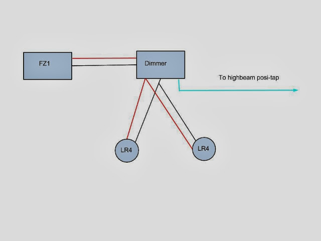
I was feeling creative, so I made a picture:

dimmer3.jpg


Basically, run the power from the FZ1 to the dimmer, attach the light leads to the output wires. The blue wire will attach to your highbeam (and/or horn) if you want to use that feature. There is no need for a separate switch, as it's built into the knob. Of course, you could add another switch if you wanted, for example if you didn't want to re-adjust the dimmer setting every time you turned it off.

Note: If you do attach the bypass to your horn, you will need to add a diode to that wire, or it will go off with your highbeams :) .

 
Last edited by a moderator:
I wanted to post a picture, and followed the directions, but when I click on the "image" button and get the dialog box and paste the "IMG" link, the screen "grays out" and will not let me do anything. What am I doing wrong?

 
Top